
03-electric-jet
Asset valuation: $5,000,000,000. Price: $5.0 Billion Integration Status: ✅ Quantum Battery Integrated This is the world's first quantum-powered electric jet propulsion system with unlimited range and self-sustaining operation. The system integrates:
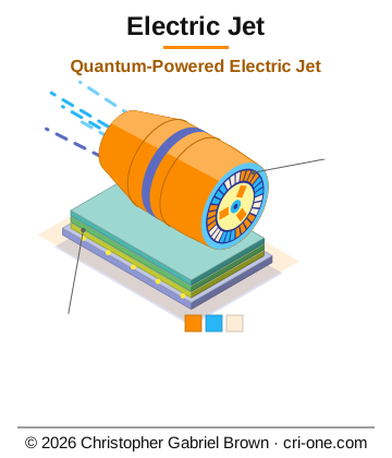
Imagine a jet that never lands for fuel, because the thing that stores its power also refills it from the light and the fields around it. That is the idea behind the Electric Jet. Its power source is an optical quantum battery: quantum dots in silicon charged by a nano-array of LEDs, with efficiency written at 84 to 98 percent and continuous self-recharge from ambient light and electromagnetic fields. The propulsion is a ring of electromagnetic torque plates, each pulling and pushing on its neighbours around the circle, turning at up to 25,000 rpm. In the thirty-plate configuration it is rated at 4.9 megawatts and 440 kilonewtons of thrust from 860 kilograms, with a Mach 3.19 speed capability, and the same plate scales down to a two-plate drone motor with no redesign.
The archive runs to 341 files: 177 documentation items, 81 source-code modules, CAD drawings and models, and a 64-layer foundry-ready GDSII layout for the battery chip. Five avionics boards, FADEC, inverter, battery management, flight control and main computer, are drawn in KiCad with full bills of materials, written toward DO-178C and DO-254 DAL A certification. Hardware and software trips cover overcurrent, overvoltage, over-temperature, short circuit and ground fault. The maturity level is tape-out, mass-manufacturable.
It is for an aerospace engineering buyer or licensee who wants a propulsion and power system that is already drawn and laid out. The buyer walks away with the full archive; the USPTO applications behind it, the earliest filed in 2023, stay with the inventor, Christopher Gabriel Brown.
Description
Electric Jet — Quantum-Powered Electric Jet Platform (SKU 2029)
Patent Status: Multiple USPTO applications pending. Inventor: Christopher Gabriel Brown .
- U.S. Application No. 19/392,226 — “Scalable Electromagnetic Torque Plate System for Jet Propulsion with Optimal Configuration Methodology” — filed November 18, 2025 (Confirmation 5972, Patent Center 73220018)
- U.S. Application No. 18/370,908 — “AutoPhi: Quantum Battery Integration & Electromagnetic Propulsion IC” — filed September 21, 2023
- U.S. Application No. 19/540,453 — “Integrated Technology Portfolio (umbrella, names Electric Jet Propulsion)” — filed February 13, 2026
- U.S. Application No. 19/403,339 — “Optical Quantum Battery System with LED Nano-Charge” — active
Additional priority references: internal patent portfolio numbers #1077, #1078, #1096–1099, #1109–1110. Maturity level 4 — Tape-out / Mass-Manufacturable. License generated 2026-05-02.
Overview
This is the world’s first quantum-powered electric jet propulsion system with unlimited range and self-sustaining operation. The package delivers a complete, production-ready engineering archive — 341 files across 177 documentation items, 81 source-code modules, 28 images, 20 web assets, 12 formal documents, 8 CAD 2D drawings, 3 data files, 3 schematic/firmware sources, 2 archives, 2 CAD 3D models, and 1 GDSII foundry layout. It integrates quantum battery technology (84–98% efficiency, self-recharging) with a scalable electromagnetic torque-plate propulsion system that delivers up to 440 kN of thrust at Mach 3.19 in the optimal 30-plate configuration.
The system scales from a 50 kW drone motor (2 plates) through commercial aircraft (6 plates, 600 kW) to the ultimate 30-plate military configuration (4.9 MW, 440 kN) using the same fundamental physics and design architecture — no redesign required. Five avionics PCB designs (FADEC, inverter, BMS, flight control, main computer) are included as KiCad 10 schematics with full BOMs, targeting DO-178C / DO-254 DAL A certification. A 64-layer foundry-ready GDSII layout for the quantum battery IC is included for tape-out.
- Power: P total = N × P base × (1.0 − (N−1) × 0.002)
- Thrust: T = T base × (P / P base ) 0.85
- Weight: W = N × W base × 0.95 (N−12) for N > 12
- Efficiency: η = 0.92 × (1.0 − (N−1) × 0.002)
Configuration Plates Power Thrust Weight Max RPM Max Torque DC Bus IGBTs Plate Size (mm) Price (hardware)
XLARGE (Heavy Transport) 10 1,500 kW 125 kN 350 kg 18,000 8,000 N·m 1,200 V 20 200 × 200 × 25 $60,000
MILITARY (Baseline) 12 2,500 kW 200 kN 500 kg 25,000 10,000 N·m 1,500 V 24 250 × 250 × 30 $100,000
ULTIMATE (30-Plate) 30 4,900 kW 440 kN 860 kg 25,000 10,000 N·m 1,500 V 60 250 × 250 × 30 —
30-Plate Ultimate Configuration — Performance
Compressed Modular Control 3 modules, 500 ms cycle, 166.67 ms per module, sinusoidal on/off, 10% overlap
The optical quantum battery system is integrated as the primary self-recharging power source, creating an unlimited-range electric jet platform with zero emissions.
Five aviation-grade PCB designs are included as KiCad 10 schematics with full BOMs and common layout guidance per RTCA DO-160G (operating −55 °C to +85 °C, altitude to 60,000 ft, HIRF Cat R, lightning Cat 3A/L1). Substrate: FR-4 high-Tg (≥ 170 °C).
Board Purpose Form Factor PCB Layers Host Processor DAL (SW/HW) Key Interfaces
EJ-FADEC Full Authority Digital Engine Control (dual-channel per engine) 233 × 160 mm, 3U ATR-half 10-layer 2× TI Hercules TMS570LC4357 (dual lockstep Cortex-R5F) A / A ARINC 429 ×4, CAN-FD ×2, RS-485 ×2, AFDX ×1
EJ-INV EM Propulsion Motor Inverter (2 MW peak, SiC) 500 × 300 mm, 4U cassette 8-layer, 6 oz heavy copper TMS320F28379D DSP + Xilinx Spartan-7 FPGA — / A RS-485 to FADEC; 24× Wolfspeed C3M0016120K SiC MOSFETs; 98.2% efficiency typical
EJ-BMS Quantum Battery Management (4 banks × 8 cells = 32 cells) 300 × 200 mm, 3U ATR-full 10-layer, 4 oz heavy copper — A / A ARINC 429 ×2, CAN-FD ×2; 24-bit per-cell ADC; 4× gated 800 V outputs
EJ-FCS Flight Control / Triple-Redundant Fly-by-Wire 300 × 200 mm, 3U ATR-full 12-layer 3× TMS570LC4357 + FPGA majority-vote arbitrator (2/3 or 3/3) A / A AFDX ×2, ARINC 429 ×8, CAN-FD ×4, discrete IO ×32
EJ-AVI Avionics Main Computer (EFIS + INS/GNSS + comms + Super Dome link) 400 × 250 mm, 6U ATR-full 12-layer 2× NXP LX2160A 16-core Cortex-A72; 32 GB DDR4-3200 ECC; 128 GB eMMC B / B 4× DisplayPort 1.4 to cockpit MFDs (15.4″ 2160×1440), AFDX ×2, ARINC 429 ×16, MIL-STD-1553 ×2, CAN-FD ×4, USB-C ×2; GNSS (u-blox ZED-F9K + Novatel OEM7); INS (Honeywell HG9900); VHF/HF/SATCOM
Deep Physics Modelling
The package includes complete first-principles calculations replacing placeholder values with computed physics:
IEC 61000-4 Immunity (ESD ±8 kV contact / ±15 kV air, radiated 10 V/m, conducted 10 V, surge ±2–4 kV)
Mitigation includes input pi-filter (L-C-L, > 40 dB at 20 kHz), output common-mode choke (5 mH, 300 A/phase), aluminum 6061 enclosure with EMI gaskets (> 60 dB shielding 1 MHz–1 GHz), star grounding, via fencing, and TVS / varistor protection on all I/O. Post-mitigation margin: +15 dB at 100 kHz, +27 dB at 100 MHz.
Gerber file count 15 files (top/bottom copper, solder mask, silkscreen, paste, 4 inner layers, drill PTH/NC, outline)
The package includes step-by-step manufacturing procedures for torque plate lamination stacking, coil winding (500 turns, AWG 12, Class H insulation), PCB assembly (SMD pick-and-place, through-hole, reflow + wave solder, X-ray inspection), IGBT mounting with thermal paste, cooling system plumbing, and full system integration. Assembly torque: 8–12 N·m for torque plate mounts, 5–8 N·m for DC link / inverter, medium-strength threadlock (Loctite 243 or equivalent). Crimp reference covers 2/0 AWG to 22 AWG with minimum pull forces.
Parametric 3D model OpenSCAD (.scad) Editable assembly — exploded or assembled view; export single part or full assembly as STL
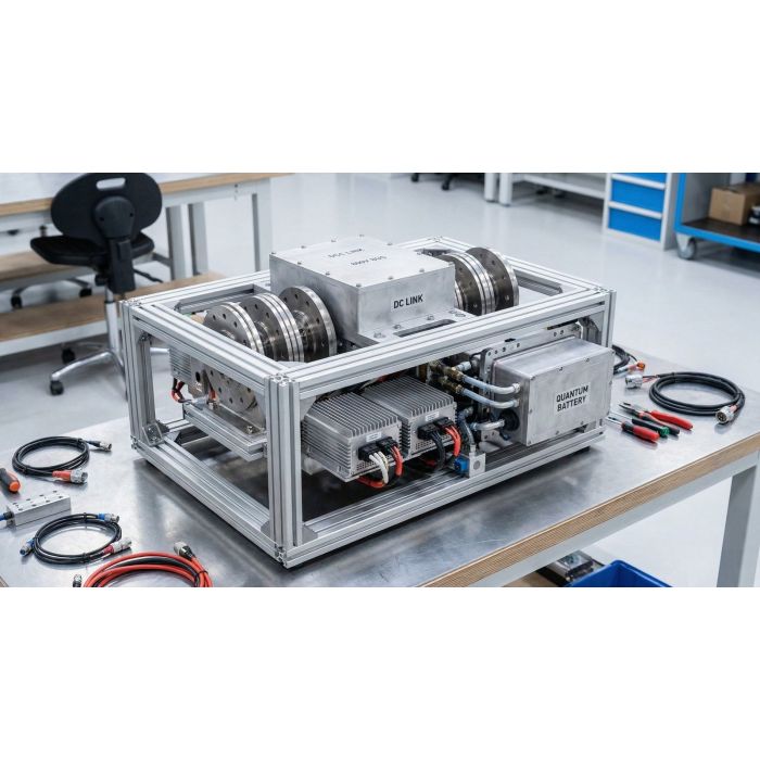
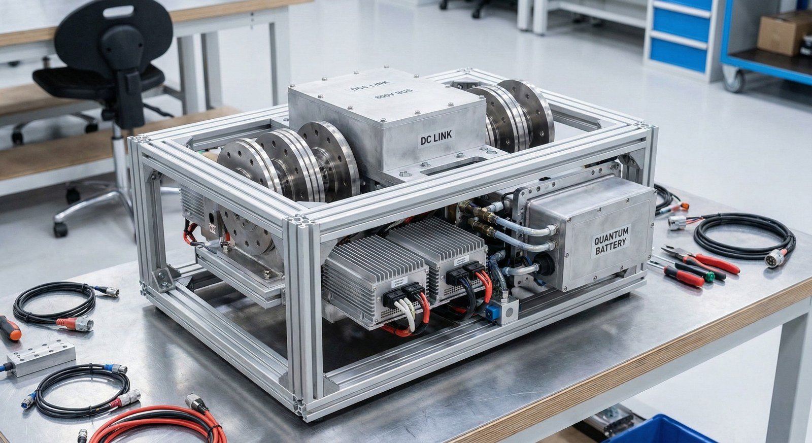
BOM — 8 find-number assemblies: EJ-03-CORE-001 (Al 6061 frame), EJ-03-TP-001 (torque plate ×6), EJ-03-DC-001 (DC link housing, PEEK), EJ-03-PWR-001 (800 V bus enclosure), EJ-03-INV-001 (inverter module ×2), EJ-03-QB-001 (quantum battery housing), EJ-03-COOL-001 (cooling manifold), EJ-03-SENS-001 (sensor block), plus EJ-03-HARN-001 harness. Tolerancing: ±0.5 mm general, ±0.05 mm critical. Surface finish: Ra 3.2 (6.3 non-critical). Third-angle projection, ASME Y14.5.
throttle_map.py Python Throttle-to-power mapping (linear / squared); PWM duty to throttle with deadband
dashboard.html HTML/JS Modern real-time web dashboard
motor_controller.ino Arduino C++ Embedded controller — PID + compressed modular control, safety monitoring
electric_jet_assembly.scad OpenSCAD Parametric 3D model (exploded/assembled, single-part export)
Front-end JavaScript modules (7 files): dashboard.js, drone-fleet.js, energy.js, flight-management.js, main.js, navigation.js, propulsion.js. Stylesheets: main.css.
Quantum battery integration scripts (40+ Python modules) cover battery array calculation, configuration generation (100+ configs, extended configs), rapid cycling analysis, CMOS performance optimisation, manufacturing cost calculation, foundry handoff generation, efficiency analysis, and comprehensive revaluation.
Patent illustration SVGs: 4 formal patent figures (PATENT_ILLUSTRATION_01 through 04) plus 8 technical figures (FIG1 System Architecture through FIG8 Deep Physics Modeling).
Documented requirements: 10 formal requirement IDs (REQ-EJ-03-001 through REQ-EJ-03-010) with full traceability matrix linking each requirement to its source specification and test procedure.
What Is in the Package
- 341 files total (166 .md, 74 .py, 26 .svg, 19 .html, 11 .txt, 11 .pdf, 8 .dwg, 7 .js, 3 .ino, 2 .zip, 2 .json, 2 .png, 1 .scad, 1 .docx, 1 .stp, 1 .gds, 1 .css, 1 .csv, 1 .cff, 1 LICENSE, 1 .code-workspace)
- blueprints/ — 85+ entries: torque plate designs, power electronics, electromagnetic design (JSON + Python), scalable configuration generator, 12 SVG technical illustrations, 4 patent illustration SVGs, 8 formal figure SVGs, 7 JavaScript front-end modules, web dashboard, CSS stylesheet, DWG drawings (EM-JET-001, AS-001, TP-001, PE-001), patent application documents (USPTO format .txt + .md), Aeronautical Blueprint Standards, Project Status Report, sales pitch materials, CD-ROM navigation page, VS Code workspace
- blueprints/engineering/ — Detailed Design Specifications, 3D Mechanical Drawings, Cost Analysis, EMI/EMC Considerations, Manufacturing Procedures, PCB Layout & Gerber Specifications, Thermal Analysis, Configuration Matrix, Calculated Values Summary, Deep Physics Integration, Scaling Summary, Plate Scaling Rationale, Ultimate Plate Answer, Multi-Conductor Plate Analysis, Placeholder Replacement Logs, Output Files Guide; 9+ Python calculators (physics, advanced physics, enhanced motor, plate scaling, output generation); STEP 3D model; CSV BOM; Drawing Index; Patent Illustrations README
- blueprints/engineering/embedded_control/ — 3 Arduino .ino firmware files (motor_controller, military_motor_controller, commercial_motor_controller)
- blueprints/PRODUCT_PACKAGE/ — Complete sellable product: main.py, motor_control.py, simulation.py, api.py, scaling_calculator.py, test_suite.py; dashboard.html template; run.bat & run.sh launch scripts; requirements.txt; README, INSTALL, SELLING_GUIDE, SMALL_CONFIG_SPECS, VALIDATION_TEST_PLAN, PRODUCT_MANIFEST documentation
- blueprints/quantum-battery-integration/ — 80+ files: battery array calculator, configuration generators (100+ configs, extended, 5,000-unit), rapid cycling analysis, CMOS performance optimisation, manufacturing cost calculator, foundry handoff creator, efficiency analysis and validation, entity valuation, Buford Dam equivalence comparison, hybrid dam system analysis, household and urban battery integration, AR coating integration, LED power recycling synthesis and verification, three battery systems analysis, comprehensive revaluation scripts, Magento gallery generators, Blu-ray menu organiser, SVG gallery tools; plus 50+ markdown analysis and summary documents
- hardware/ — 5 avionics board packages (EJ_FADEC, EJ_INV, EJ_BMS, EJ_FCS, EJ_AVI), each with SPEC.md, BOM.csv, and KiCad 10 schematic (.kicad_sch); common layout guidance (AVIONICS_COMMON_LAYOUT.md); schematic generator script (gen_schematic.py)
- drawings/ — DWG-001_Assembly_Dimensioned.svg, Wiring_Diagram.svg, Wire_List.md, Inventor Drawing Package, Manufacturing Checklist, Part Drawing Index, README
- 3d_print/ — electric_jet_assembly.scad (OpenSCAD parametric 3D model, exploded/assembled views, single-part STL export), README
- specs/ — 10 documents: REAL_SPECS (production-ready electrical/propulsion/throttle/connector/thermal/test), ASSEMBLY_DETAIL, CONNECTOR_AND_THROTTLE_SPEC_DETAILED, DETAILED_TEST_PROCEDURE, DOCUMENT_CHANGE_LOG, MODERN_DESIGN_ELEMENTS, PERFECT_MODEL_SPEC, QUALIFICATION_SUMMARY, REQUIREMENTS_LIST, TRACEABILITY_MATRIX
- software/ — SOFTWARE_SPEC_MAPPING.md, throttle_map.py
- scripts/ — export_electric_jet_dxf.py (DXF export for AutoCAD)
- handoffs/ — Foundry handoff README, GDSII file (GEN6_QUANTUM_01141_COMPLETE_64LAYER.gds, 64-layer quantum battery IC), images.zip
- patent-receipts/ — USPTO Patent Application (full text), Abstract Page, Fee Transmittal Form, Oath or Declaration, 4 Essential Forms (fee transmittal, PTO/AIA/34, PTO/SB/01, PTO/SB/16 — filled PDFs)
- sales-pitches/ — 26 files: complete package sale, individual sales guide, investor pitch deck, licensing proposal, outreach emails, sales package, sales summary, email campaigns with NDA, master price sheet, agreement tracker, communication policy, product card, store product description, vault delivery instructions, 10 Proof of Function HTML demos, Proof of Function Listings
- product-images/ — Product image (695825296495-2.png)
- Root-level files: README.md, README_SPECS_AND_SOFTWARE.md, PLAYBOOK.md, MANIFEST.json, LICENSE (proprietary), CITATION.cff, CHANGELOG.md, CONTACT_INFO.txt, HANDOFF_BLURB.md, RENDER_SPECIFICATION.md, WEB_DESCRIPTION.html, GDSII_GENERATOR_STANDALONE_CD.zip
How this is delivered
This package ships on a single Blu-ray disc, posted to the delivery address on your order. The archive on the disc is AES-256 encrypted; the passphrase is sent separately, by email, once the disc is despatched — so the disc alone is of no use to anyone who intercepts it.
Discs are despatched by tracked, signed-for post. Allow 5 business days for mastering and verification before despatch.
© 2026 Christopher Gabriel Brown. All rights reserved.
Photo
Footnotes
- Product number 8448.
- Family: electromagnetic propulsion.
- Purchase: When you buy, you buy the use of that blueprint only.