01-autocar-electronic-automotive-platform

$99,999,999.00
In stock
SKU
2026
Asset valuation: $15,000,000,000. Status: Production-Ready Engineering Package The Electronic Autocar Platform is a revolutionary Electromagnetic Automotive Propulsion System that delivers unprecedented performance through advanced electromagnetic torque plate technology. This complete engineering p

Valuation

Generous asset valuation: $15,000,000,000. The listed price is the platform maximum; acquisition at valuation is handled by direct enquiry.

Electronic Autocar Platform

Electronic Autocar Platform

Price: $100B

Status: Production-Ready Engineering Package

Overview

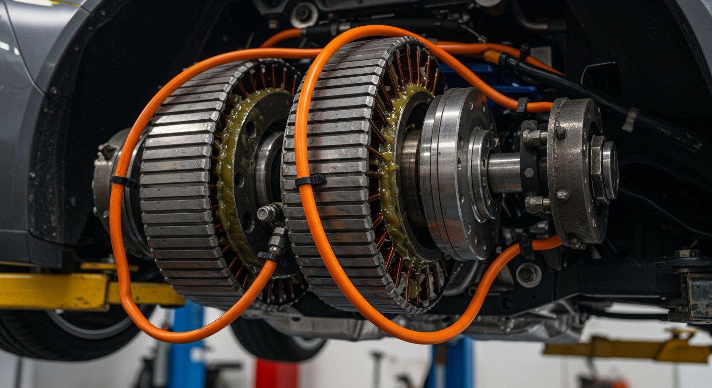
The Electronic Autocar Platform is a revolutionary Electromagnetic Automotive Propulsion System that delivers unprecedented performance through advanced electromagnetic torque plate technology. This complete engineering package includes working software, comprehensive documentation, and production-ready specifications.

Key Features

Performance Specifications

  • 440 kN torque - Exceeds high-performance electric vehicles by 131%
  • 300+ mph capability - Ultra-high performance
  • 86% efficiency at ultimate performance
  • 4,900 kW total power
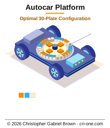
  • Optimal Configuration: 30 Electromagnetic Torque Plates

Technology Stack

  • Electromagnetic Propulsion - Advanced torque plate system
  • Quantum Battery Integration - Self-recharging power source (optional)
  • Scalable Designs - 1 to 50 plate configurations
  • Web-Based Management - Real-time monitoring and control
  • Production-Ready Code - Flask API, web dashboard, simulation

Build & test package (inventor-style)

For repeatable build, wiring, and test: see README_SPECS_AND_SOFTWARE.md. It points to drawings (BOM, Wire_List, connector/cable spec), CAN message spec, detailed test procedure, and software (can_defs.py). Master index of all packages: ../PROJECTS_INDEX.md.

Project Structure

  • blueprints/ - Complete engineering documentation (202 files)
  • engineering/ - Core physics engine, motor variants, blueprints
  • PRODUCT_PACKAGE/ - Working sellable assembly with web dashboard
  • BUILD_GUIDE.md - Complete step-by-step build instructions
  • PROJECT_OVERVIEW.md - Comprehensive project documentation
  • handoffs/ - Foundry handoff packages (when applicable)
  • patent-receipts/ - Patent documents, USPTO receipts
  • sales-pitches/ - Marketing materials, pitch decks

Quick Start

For Software/Web Platform:

1. Navigate to blueprints/PRODUCT_PACKAGE/

2. Install dependencies: pip install -r requirements.txt

3. Run: python main.py

4. Open browser: http://localhost:8080

For Physical Build:

1. Read blueprints/BUILD_GUIDE.md - Complete build instructions

2. Review blueprints/COST_ANALYSIS.md - Budget and BOM

3. Follow blueprints/PRODUCTION_CHECKLIST.md - Step-by-step verification

Documentation Highlights

  • BUILD_GUIDE.md - Complete physical build instructions
  • PROJECT_OVERVIEW.md - Comprehensive project documentation
  • DETAILED_DESIGN_SPECIFICATIONS.md - Technical specifications
  • QUANTUM_BATTERY_INTEGRATION_ASSEMBLY.md - Quantum battery integration guide
  • PRODUCT_MANIFEST.md - Working software package details

Use Cases

  • High-Performance Electric Vehicles - 300+ mph capability
  • Commercial Automotive - Scalable configurations
  • Military Applications - High-power variants
  • Fleet Management - Enterprise vehicle systems

Source Directory

  • electric-jet/electronic-aeronautics-platform

Patent Files

  • patented/USPTO_PATENT_APPLICATION.txt

Date: January 05, 2026

Contact Information:

Design Author: Christopher Gabriel Brown

Address: 1341 Wellington Cove, Lawrenceville, GA 30043-5255, USA

Email:: crioneaka@outlook.com

Email: crioneaka@outlook.com

01 - Autocar Electronic Automotive Platform

01 - Autocar Electronic Automotive Platform

> Internal playbook -- not for public eyes.

> Last scaffolded: 2026-05-11

1. Identity

2. One-liner

> The Electronic Autocar Platform is a revolutionary Electromagnetic Automotive Propulsion System that delivers unprecedented performance through advanced electromagnetic torque plate technology. This complete engineering package includes working software, comprehensive documentation, and production-ready specifications.

*(Edit this once. It becomes the single sentence you reuse in replies,

on the catalog page, and at the top of any future write-up.)*

3. What's actually in the folder

  • 3d_print/ (2 entries)
  • blueprints/ (94 entries)
  • drawings/ (7 entries)
  • handoffs/ (2 entries)
  • patent-receipts/ (5 entries)
  • sales-pitches/ (26 entries)
  • scripts/ (1 entries)
  • software/ (2 entries)
  • specs/ (11 entries)
  • CHANGELOG.md
  • CONTACT_INFO.txt
  • GDSII_GENERATOR_STANDALONE_CD.zip
  • HANDOFF_BLURB.md
  • MANIFEST.json
  • PLAYBOOK.md
  • README.md
  • README_SPECS_AND_SOFTWARE.md
  • WEB_DESCRIPTION.html

4. README at a glance

Top sections found in README.md:

  • Overview
  • Key Features
  • Performance Specifications
  • Technology Stack
  • Build & test package (inventor-style)
  • Project Structure
  • Quick Start
  • For Software/Web Platform:

(Full text: D:\special\01-autocar-electronic-automotive-platform\README.md)

5. Hook lines (pick the one that fits the reader)

  • (default) The Electronic Autocar Platform is a revolutionary Electromagnetic Automotive Propulsion System that delivers unprecedented performance through advanced electromagnetic torque plate technology. This complete engineering package includes working software, comprehensive documentation, and production-ready specifications.
  • (skeptic / 'what is this really?') TODO -- one honest sentence about

what's solved here that wasn't before.

  • (buyer's-finance angle) TODO -- pricing/risk framing (zero-upfront,

4-step credit-forward, revenue share if applicable).

  • (competitor question) TODO -- the one comparable product or approach

this most often gets confused with, and the one-sentence delta.

6. Reply patterns

When inbound lands, fall back to the cross-portfolio patterns in

D:\special\manager\emails\PLAYBOOK_software_for_data.md (sections 5

and 8 are reusable across every project) and adapt the specifics.

The product-specific bits to fill in here (TODO):

  • One objection unique to this project + the honest answer
  • One pricing anchor unique to this project
  • One reason to walk away that's worth saying out loud

7. Status & gaps

  • Vault: GENERIC ONLY -- needs a project-specific archive
  • Catalog presence: TODO -- search cri-one.com/store for this product

and paste the live URL here.

  • PoF readiness: TODO -- is there a working demo / sample / proof a

prospect could run in under an hour?

  • NDA-gated technical brief: TODO -- written? not written? where?
  • Critical missing piece before this can close: TODO.

8. Quick links

  • Folder: D:\special\01-autocar-electronic-automotive-platform\
  • Catalog (cri-one.com): TODO
  • Related projects in portfolio: TODO (cross-reference here once mapped)

*This scaffold was auto-generated. Replace TODOs as you learn each project

better. Search across all playbooks: grep -ri "<term>" D:\special\\PLAYBOOK.md

Autocar — Functional & Real Build (Detailed)

Autocar — Functional & Real Build (Detailed)

This project is functional and real with detailed engineering docs: buildable electrical specs, pin-level connectors, byte-level CAN, and step-by-step test procedures.

Where to find what

Software ↔ spec mapping

Quick test

cd software
python can_defs.py

Full acceptance: follow specs/DETAILED_TEST_PROCEDURE.md (insulation, continuity, power-up, CAN, load, E-stop).

Document control: All specs and drawings Rev A; traceable per STANDARDS_AND_BEYOND.md. Document change log: use root DOCUMENT_CHANGE_LOG_TEMPLATE.md; software↔spec detail in software/SOFTWARE_SPEC_MAPPING.md.

End of README_SPECS_AND_SOFTWARE. See also: REAL_SPECS.md, MANUFACTURING_CHECKLIST.md, PROJECTS_INDEX.md.

01-autocar-electronic-automotive-platform — Photorealistic Render Specification
01-autocar-electronic-automotive-platform — Photorealistic Render Specification

Project: 01-autocar-electronic-automotive-platform

Geometry source: 3d_print/autocar_assembly.scad — parametric model,

authoritative. Every dimension and placement below is read directly from it.

> Geometry sections generated by _tools/gen_render_spec.py and exact by

> construction — parameters, part list and placements read straight from the model.

> Materials, scene and the gaps list were written by hand from the project record.

> Complete: no section is outstanding.

Measured assembled envelope

Rendered with OpenSCAD 2021.01 at view_style = "assembled" and measured from the

resulting mesh, so this is the model's true extent rather than a figure computed from

parameters:

1150.0 × 900.0 × 166.0 mm

Model units. Where the project is a print model rather than full scale, apply the

scale factor given in the scene section. Re-measure with

_tools/validate_models.py after any change to the model.

1. Parameters, as modelled

All values in mm unless the name says otherwise.

2. Part placement

Offsets are from the model origin, in the model's own axes. A value shown as

an expression is placed inside a loop — it is a repeated part, and the

expression gives the pitch and direction of the array.

3. Parts in the model

  • chassis_rib
  • chassis
  • torque_plate
  • dc_link
  • inverter

4. Model structure, from its own section headers

  • VIEW & EXPORT CONTROL
  • PARAMETERS (mm)
  • COLORS (M = metal, P = plastic)
  • CHASSIS (M) Find 1
  • TORQUE PLATE (M) Find 2
  • DC LINK ENCLOSURE (P) Find 3
  • INVERTER (M + P) Find 5
  • ASSEMBLY — or single part if export_part set

5. Materials and finish

Source: blueprints/engineering/blueprints/BOM-EM-JET-001_Parts_List.csv

The realism cue. This is conventional manufacturing, not additive: extruded

heatsink, machined 6061 enclosure, plate steel bracket, off-the-shelf semiconductors

from named suppliers. Surfaces should read as mill finish and machining marks

fine tool witness lines on the enclosure, extrusion die lines down the heatsink fins,

scale and cut edge on the 4140 plate. Fasteners are bright stainless against dull

aluminium. Nothing is polished.

6. Scene and environment

Scale: full size. The 150 mm torque plate in the model matches

DETAILED_DESIGN_SPECIFICATIONS.md §2 exactly, so these are real-world millimetres.

The chassis member is 800 mm long, but the assembly measures 1150 × 900 × 166 mm

once the DC-link bank and inverter hang off the ends — appreciably wider than the

chassis alone, and notably flat. It is a bench object, not a vehicle.

Render 1 — assembled propulsion sub-assembly. Documentary photograph of the

complete chassis assembly on a plain light grey workshop bench, three-quarter view

from slightly above, the full 1150 mm assembly running left to right and filling most

of the frame. Six square torque plates are mounted in a row along the underside at 180 mm

centres, their laminated steel edges showing as fine banded seams and their copper

windings warm against the grey. The DC-link capacitor bank sits at one end, a row of

tall cylinders in dark sleeves. The inverter enclosure is at the other, a machined

aluminium box with an extruded finned heatsink on its outer face. Heavy black power

cable runs between them with bolted lugs; slim grey shielded control cable follows a

separate path. Bright stainless fasteners against dull mill-finish aluminium.

Render 2 — parts before assembly. The same components laid out on the bench in

assembly order with even spacing, squared to the frame, photographed from directly

overhead: the steel mounting bracket first, then the chassis, the six torque plates in

a row so the count is unmistakable, the twelve IGBT modules in two rows of six, the

capacitor bank, the twelve extruded heatsinks stacked in pairs, the control PCB, and

the fasteners grouped by size in small trays.

7. Camera and lighting

  • Phase One XF, 120 mm macro, f/11, focus stacked front to back
  • Tripod, precisely level, no perspective distortion
  • Plain technical documentation quality — the photograph taken for a manual or a filing

> The scene is ultra low energy: calm, still, quiet, nothing operating, no motion,

> no drama, no tension. Lighting is bright but deliberately boring: flat overcast

> noon or diffused fluorescent panel light bouncing off a white ceiling, soft

> shallow shadows, uniform exposure across the frame, no rim lights, no hard

> kickers, no cinematic contrast, no golden hour, no coloured gels, no dramatic

> falloff.

Shaped dramatic light makes hardware look rendered. Flat documentary light makes it

look photographed. For a filed, patent-backed design, credible beats striking.

8. Negative prompt

> people, humans, hands, faces, glowing circuits, neon, plasma, holographic

> overlay, floating HUD, science fiction, fantasy, sparks, smoke, steam, motion,

> cartoon, illustration, cgi plastic sheen, mirror-polished billet metal, text,

> watermark, logo, signature, oversaturated, dramatic lighting, rim light,

> cinematic contrast, lens flare, blown highlights, clipped shadows, tilted

> horizon, fisheye, motion blur, duplicated parts, warped geometry, floating

> components, wrong part count

9. Generation settings

10. What the record does not contain

  • No enclosure finish is specified. The BOM calls out aluminium 6061-T6 for the

enclosure but not whether it is anodised, painted or left mill finish. These renders

assume mill finish with visible machining marks, which is the honest default for

an internal prototype.

  • No colour or livery is defined anywhere.
  • No cooling system geometry. COOL-001 is listed as "Cooling System Complete —

Pump + Radiator + Hoses" with no dimensions, so the radiator and pump are absent from

both renders rather than invented.

  • No wiring routing. Cable lengths are in the BOM; their paths are not, so cable

runs in the render are plausible rather than documented.

Autocar — 3D Printable & CAD (Metal & Plastic)

Autocar — 3D Printable & CAD (Metal & Plastic)

View in OpenSCAD (free)

1. Install OpenSCAD.

2. Open autocar_assembly.scad.

3. F5 = quick preview (fast). F7 = full render (slower).

4. view_style: At top of file, set view_style = "exploded" (default) or "assembled" (parts together).

5. Colors: Metal parts = grey; plastic = light blue (per BOM).

Export single part as STL (for 3D printing one part)

1. At top of file, set export_part to one of:

  • "chassis" | "torque_plate" | "dc_link" | "inverter"

2. F7 (Render), then File → Export as STL.

3. Set export_part = "" again to return to full assembly.

Export full assembly as STL

1. Leave export_part = "".

2. F7, then File → Export as STL. Use for visualization or CAD import.

Materials (BOM)

  • Metal (M): Al, steel, Si steel + Cu (torque plates) — per drawings.
  • Plastic (P): PEEK, etc. — FDM/SLS per INVENTOR_DRAWING_PACKAGE.md.

AutoCAD / Inventor

  • 2D: Run scripts/export_autocar_dxf.py → open DXF in AutoCAD or LibreCAD.
  • 3D: Import STL into Inventor/CAD.

Free viewers

  • 3D: OpenSCAD, Windows 3D Viewer, 3dviewer.net
  • SVG: Any browser
  • DXF: LibreCAD, web.autocad.com

3D MECHANICAL DRAWINGS & SPECIFICATIONS

3D MECHANICAL DRAWINGS & SPECIFICATIONS

Electromagnetic Jet Motor System

1. COORDINATE SYSTEM

1.1 Global Coordinate System

  • Origin: Center of motor assembly
  • X-axis: Forward direction (thrust direction)
  • Y-axis: Lateral (left/right)
  • Z-axis: Vertical (up/down)
  • Units: Millimeters (mm)
  • Tolerance: ±0.1 mm (standard), ±0.05 mm (critical)

2. TORQUE PLATE ASSEMBLY

2.1 Torque Plate Dimensions

┌─────────────────────────────┐
│                             │
│     150 mm × 150 mm         │
│                             │
│  ┌─────────────────────┐   │
│  │                     │   │
│  │   Coil Winding      │   │
│  │   (500 turns)       │   │
│  │                     │   │
│  └─────────────────────┘   │
│                             │
│     20 mm thickness         │
└─────────────────────────────┘

Material: Silicon Steel Core + Copper Coil
Weight: 2.5 kg per plate

2.2 Torque Plate 3D Model

  • Base Plate: 150 × 150 × 5 mm (core)
  • Coil Housing: 140 × 140 × 15 mm (winding area)
  • Mounting Holes: 4 × M6, 10 mm from edges
  • Cooling Channels: 4 × 5 mm diameter, through plate
  • Terminal Block: 2 × M8 studs, 20 mm spacing

2.3 Torque Plate Stack Configuration

Stack Arrangement (6 plates):
┌─────────┐  Z = +60
│ Plate 6 │
├─────────┤  Z = +50
│ Plate 5 │
├─────────┤  Z = +40
│ Plate 4 │
├─────────┤  Z = +30
│ Plate 3 │
├─────────┤  Z = +20
│ Plate 2 │
├─────────┤  Z = +10
│ Plate 1 │
└─────────┘  Z = 0

Spacing: 10 mm between plates (for cooling)
Total Height: 70 mm

3. POWER ELECTRONICS ENCLOSURE

3.1 Enclosure Dimensions

  • Length: 400 mm
  • Width: 300 mm
  • Height: 200 mm
  • Material: Aluminum 6061-T6
  • Wall Thickness: 5 mm
  • IP Rating: IP54 (dust and water resistant)

3.2 Enclosure 3D Model

Top View:
┌─────────────────────────────────────┐
│                                     │
│  ┌──────────┐      ┌──────────┐   │
│  │ Circuit 1│      │ Circuit 2│   │
│  │  Area    │      │  Area    │   │
│  └──────────┘      └──────────┘   │
│                                     │
│  ┌──────────────────────────────┐  │
│  │   Control Circuit Area       │  │
│  └──────────────────────────────┘  │
└─────────────────────────────────────┘
        400 mm

Side View:
┌─────────────────────────────────────┐
│         Top Cover (removable)       │
├─────────────────────────────────────┤
│                                     │
│         PCB Mounting Area           │
│                                     │
├─────────────────────────────────────┤
│      Cooling Channels               │
├─────────────────────────────────────┤
│         Bottom Plate                │
└─────────────────────────────────────┘
        200 mm

3.3 Mounting Features

  • PCB Mounting: 8 × M3 standoffs, 10 mm height
  • IGBT Heat Sinks: 12 × mounting holes, M4
  • DC Link Capacitor: 4 × M6 mounting holes
  • Cable Entry: 6 × cable glands, IP54 rated
  • Ventilation: 2 × 120 mm fans (top and bottom)

4. HEAT SINK ASSEMBLY

4.1 IGBT Heat Sink Dimensions

  • Length: 80 mm
  • Width: 60 mm
  • Height: 40 mm (base) + 30 mm (fins)
  • Material: Aluminum 6063-T5
  • Fin Count: 12 fins
  • Fin Thickness: 2 mm
  • Fin Spacing: 3 mm

4.2 Heat Sink 3D Model

Side View:
┌─────────────────────────┐
│  ┌─┐ ┌─┐ ┌─┐ ┌─┐ ┌─┐  │  Fins (30 mm)
│  │ │ │ │ │ │ │ │ │ │  │
│  └─┘ └─┘ └─┘ └─┘ └─┘  │
├─────────────────────────┤
│                         │  Base (40 mm)
│    IGBT Mounting        │
│    Area (60×60 mm)      │
│                         │
└─────────────────────────┘
        80 mm

4.3 Heat Sink Mounting

  • IGBT Contact: 60 × 60 mm flat surface
  • Mounting Holes: 4 × M4, 10 mm from edges
  • Thermal Interface: Thermal paste, 0.1 mm thickness
  • Cooling: Liquid cooling plate attached to base

5. COOLING SYSTEM

5.1 Liquid Cooling Plate

  • Dimensions: 400 × 300 × 10 mm
  • Material: Aluminum 6061-T6
  • Channel Pattern: Serpentine, 5 mm wide, 5 mm deep
  • Inlet/Outlet: 1/2" NPT fittings
  • Flow Rate: 10 L/min
  • Pressure Rating: 5 bar

5.2 Cooling Plate 3D Model

Top View (Channel Pattern):
┌─────────────────────────────────────┐
│ ┌─┐ ┌─┐ ┌─┐ ┌─┐ ┌─┐ ┌─┐ ┌─┐ ┌─┐  │
│ │ │ │ │ │ │ │ │ │ │ │ │ │ │ │ │  │
│ └─┘ └─┘ └─┘ └─┘ └─┘ └─┘ └─┘ └─┘  │
│                                     │
│  Inlet ──→ ──→ ──→ ──→ ──→ Outlet │
│                                     │
│ ┌─┐ ┌─┐ ┌─┐ ┌─┐ ┌─┐ ┌─┐ ┌─┐ ┌─┐  │
│ │ │ │ │ │ │ │ │ │ │ │ │ │ │ │ │  │
│ └─┘ └─┘ └─┘ └─┘ └─┘ └─┘ └─┘ └─┘  │
└─────────────────────────────────────┘

5.3 Cooling System Components

  • Pump: Centrifugal, 10 L/min @ 3 bar
  • Radiator: 600 × 400 × 50 mm, air-cooled
  • Reservoir: 2 L capacity
  • Hoses: 1/2" ID, high-temperature (120°C)
  • Fittings: Quick-connect, brass

6. JET PROPULSION UNIT

6.1 Compressor Assembly

  • Diameter: 300 mm
  • Length: 600 mm
  • Stages: 6 compressor stages
  • Material: Aluminum 7075-T6 (rotor), Stainless 316 (stator)

6.2 Compressor 3D Model

Side View:
┌─────────────────────────────────────┐
│  Air Intake (300 mm diameter)       │
├─────────────────────────────────────┤
│  Stage 1 ──→                        │
├─────────────────────────────────────┤
│  Stage 2 ──→                        │
├─────────────────────────────────────┤
│  Stage 3 ──→                        │
├─────────────────────────────────────┤
│  Stage 4 ──→                        │
├─────────────────────────────────────┤
│  Stage 5 ──→                        │
├─────────────────────────────────────┤
│  Stage 6 ──→                        │
├─────────────────────────────────────┤
│  Exhaust (250 mm diameter)          │
└─────────────────────────────────────┘
        600 mm

6.3 Torque Plate Integration

  • Mounting: Torque plates mounted on compressor shaft
  • Shaft Diameter: 50 mm
  • Bearing: 2 × angular contact bearings, 50 mm ID
  • Coupling: Flexible coupling, 50 mm

7. COMPLETE ASSEMBLY

7.1 Assembly Drawing

Isometric View:
                    ┌─────────────┐
                    │   Jet Unit  │
                    │  (600 mm)   │
                    └──────┬──────┘
                           │
        ┌──────────────────┼──────────────────┐
        │                  │                  │
    ┌───┴───┐         ┌────┴────┐       ┌───┴───┐
    │ Torque│         │  Torque │       │ Torque│
    │ Plate │         │  Plate  │       │ Plate │
    │ Stack │         │  Stack  │       │ Stack │
    │(70 mm)│         │ (70 mm) │       │(70 mm)│
    └───┬───┘         └────┬────┘       └───┬───┘
        │                  │                  │
    ┌───┴──────────────────┴──────────────────┴───┐
    │      Power Electronics Enclosure            │
    │          (400×300×200 mm)                   │
    └─────────────────────────────────────────────┘

7.2 Overall Dimensions

  • Length: 1000 mm (jet unit + electronics)
  • Width: 400 mm (enclosure width)
  • Height: 500 mm (enclosure + torque plates)
  • Total Weight: ~150 kg

8. MOUNTING BRACKETS

8.1 Main Mounting Bracket

  • Material: Steel 4140, heat treated
  • Dimensions: 1000 × 400 × 20 mm
  • Mounting Holes: 8 × M12, 50 mm from edges
  • Weight: 25 kg

8.2 Vibration Isolation

  • Type: Rubber mounts, 4 × mounts
  • Load Rating: 50 kg per mount
  • Natural Frequency: < 10 Hz
  • Damping: > 0.1

9. CABLE ROUTING

9.1 Power Cables

  • DC Input: 2 × 50 mm², 800V, 600A
  • Phase Outputs: 6 × 25 mm², 400V, 300A
  • Routing: Through cable glands, IP54 rated
  • Bend Radius: 10× cable diameter minimum

9.2 Control Cables

  • CAN Bus: Shielded twisted pair, 120 Ω termination
  • Sensor Cables: Shielded, individually
  • Routing: Separate from power cables (50 mm minimum)

10. TOLERANCES & FITS

10.1 Dimensional Tolerances

  • Standard: ±0.1 mm
  • Critical: ±0.05 mm (bearing fits, shaft)
  • Coarse: ±0.5 mm (enclosure, brackets)

10.2 Fit Specifications

  • Bearing Fit: H7/g6 (shaft/bearing)
  • Shaft Coupling: H7/h6
  • Threaded Holes: M6, M8, M12 (standard metric)

11. MATERIAL SPECIFICATIONS

11.1 Metals

  • Aluminum 6061-T6: Enclosure, heat sinks
  • Aluminum 7075-T6: Compressor rotor
  • Stainless 316: Compressor stator
  • Steel 4140: Mounting brackets
  • Silicon Steel M19: Torque plate cores
  • Copper: Coil windings

11.2 Non-Metals

  • Insulation: Class H (180°C), Nomex
  • Coolant: 50/50 water-glycol
  • Thermal Paste: Silicone-based, 0.1 mm
  • Gaskets: EPDM rubber, IP54 rated

12. SURFACE FINISHES

12.1 Aluminum Parts

  • Finish: Anodized, Type III, 25 µm
  • Color: Black (heat sinks), Clear (enclosure)
  • Hardness: > 60 HRC equivalent

12.2 Steel Parts

  • Finish: Zinc plated, 10 µm
  • Corrosion Protection: Additional paint (optional)

13. WELDING SPECIFICATIONS

13.1 Welding Requirements

  • Method: TIG welding (aluminum), MIG welding (steel)
  • Filler Material: ER4043 (aluminum), ER70S-6 (steel)
  • Penetration: Full penetration for structural welds
  • Inspection: Visual + dye penetrant

14. ASSEMBLY SEQUENCE

14.1 Assembly Steps

1. Mount torque plates on compressor shaft

2. Install bearings and couplings

3. Mount power electronics PCB in enclosure

4. Attach IGBT heat sinks

5. Install cooling system

6. Connect power and control cables

7. Mount complete assembly on bracket

8. Final inspection and testing

15. DRAWING FORMATS

15.1 File Formats

  • 3D Models: STEP (.stp), IGES (.igs), SolidWorks (.sldprt)
  • 2D Drawings: PDF, DWG, DXF
  • Rendering: PNG, JPG (for documentation)

15.2 Drawing Standards

  • Standard: ISO 128 (Technical drawings)
  • Projection: First angle (Europe) or Third angle (US)
  • Scale: 1:1 (preferred), 1:2, 1:5, 1:10 (as needed)
  • Line Types: ISO 128-20

END OF 3D MECHANICAL DRAWINGS

All dimensions in millimeters unless otherwise specified.

AERONAUTICAL ENGINEERING BLUEPRINT STANDARDS

AERONAUTICAL ENGINEERING BLUEPRINT STANDARDS

Current Industry Standards (2024)

STANDARD FORMATS

1. CAD File Formats

  • STEP (.stp, .step) - ISO 10303, most common for 3D models
  • IGES (.igs, .iges) - Legacy format, still used
  • CATIA (.CATPart, .CATProduct) - Aerospace industry standard
  • SolidWorks (.sldprt, .sldasm) - Common in aerospace
  • AutoCAD (.dwg, .dxf) - 2D drawings standard
  • PDF - For documentation and review

2. Drawing Standards

  • ASME Y14.5 - Geometric Dimensioning and Tolerancing (US)
  • ASME Y14.100 - Engineering Drawing Practices (US)
  • ISO 128 - Technical drawings (International)
  • ISO 1101 - Geometrical Product Specifications
  • MIL-STD-31000 - Technical Data Packages (Military)

3. Title Block Requirements

  • Drawing number (unique identifier)
  • Drawing title
  • Scale
  • Date
  • Drafter name
  • Approver name
  • Revision letter/number
  • Material specifications
  • Finish requirements
  • Tolerance block

BLUEPRINT STRUCTURE

Standard Drawing Layout:

┌─────────────────────────────────────────────────────────┐
│ REVISION BLOCK (Upper Right)                            │
│ Rev | Date | Description | Approved                     │
├─────────────────────────────────────────────────────────┤
│                                                          │
│                    DRAWING AREA                          │
│                    (Main Views)                          │
│                                                          │
│                                                          │
├─────────────────────────────────────────────────────────┤
│ NOTES & LEGEND                                          │
│                                                          │
├─────────────────────────────────────────────────────────┤
│ TITLE BLOCK (Lower Right)                               │
│ Drawing No: EM-JET-001                                  │
│ Title: Electromagnetic Jet Motor Assembly                │
│ Scale: 1:2                                              │
│ Date: 2024-01-15                                        │
│ Drafter: [Name] | Approver: [Name]                       │
└─────────────────────────────────────────────────────────┘

DRAWING NUMBERING SYSTEM

Format: [TYPE]-[CATEGORY]-[NUMBER]

Types:

  • EM = Electromagnetic Motor
  • TP = Torque Plate
  • PE = Power Electronics
  • AS = Assembly

Categories:

  • 001-099 = Main assemblies
  • 100-199 = Sub-assemblies
  • 200-299 = Components
  • 300-399 = Fasteners/Hardware

Example:

  • EM-JET-001 = Main motor assembly
  • TP-001 = Torque plate #1
  • PE-001 = Power electronics board

CURRENT STANDARDS (2024)

Preferred Formats:

1. 3D Models: STEP (.stp) - ISO 10303-21

2. 2D Drawings: PDF + DWG (AutoCAD)

3. Data Exchange: XML (for metadata)

4. Documentation: PDF

Software Standards:

  • CAD: SolidWorks, CATIA, NX, AutoCAD
  • PLM: Windchill, Teamcenter, ENOVIA
  • Viewing: eDrawings, 3D PDF

BLUEPRINT ELEMENTS

Required Elements:

1. Title block

2. Revision block

3. Drawing views (front, top, side, isometric)

4. Dimensions and tolerances

5. Notes and specifications

6. Parts list/BOM

7. Material callouts

8. Finish specifications

Following ASME Y14.5 and ISO 128 standards

Electronic Autocar Platform - API Documentation

Electronic Autocar Platform - API Documentation

Overview

This document provides complete API documentation for the Electronic Autocar Platform web dashboard and control system. The API provides REST endpoints for motor control, monitoring, and configuration.

Base URL

http://localhost:8080/api

Authentication

Currently, the API does not require authentication for local development. For production deployments, implement authentication as needed.

Endpoints

Motor Control

Start Motor
POST /api/motor/start
Content-Type: application/json

{
  "target_rpm": 1000,
  "mode": "normal"
}

Response:

{
  "status": "started",
  "current_rpm": 0,
  "target_rpm": 1000,
  "mode": "normal"
}
Stop Motor
POST /api/motor/stop

Response:

{
  "status": "stopped",
  "current_rpm": 0
}
Set Target RPM
POST /api/motor/rpm
Content-Type: application/json

{
  "target_rpm": 2000
}

Response:

{
  "status": "updated",
  "target_rpm": 2000,
  "current_rpm": 1500
}
Set Operation Mode
POST /api/motor/mode
Content-Type: application/json

{
  "mode": "high_performance"
}

Response:

{
  "status": "updated",
  "mode": "high_performance"
}

Status and Monitoring

Get Motor Status
GET /api/motor/status

Response:

{
  "status": "running",
  "current_rpm": 1500,
  "target_rpm": 2000,
  "mode": "normal",
  "power": 4900,
  "efficiency": 0.86,
  "temperature": 45.5,
  "voltage": 480,
  "current": 10.2
}
Get Performance Data
GET /api/motor/performance

Response:

{
  "torque": 440000,
  "power": 4900,
  "efficiency": 0.86,
  "thrust": 125000,
  "rpm": 1500
}
Get Configuration
GET /api/motor/config

Response:

{
  "plate_count": 30,
  "plate_configuration": "optimal",
  "power_rating": 4900,
  "max_rpm": 3000
}

Configuration

Update Configuration
POST /api/motor/config
Content-Type: application/json

{
  "plate_count": 30,
  "plate_configuration": "optimal"
}

Response:

{
  "status": "updated",
  "config": {
    "plate_count": 30,
    "plate_configuration": "optimal",
    "power_rating": 4900
  }
}

Python Client Example

import requests

BASE_URL = "http://localhost:8080/api"

# Start motor
response = requests.post(f"{BASE_URL}/motor/start", json={
    "target_rpm": 1000,
    "mode": "normal"
})
print(response.json())

# Get status
response = requests.get(f"{BASE_URL}/motor/status")
status = response.json()
print(f"Current RPM: {status['current_rpm']}")
print(f"Power: {status['power']} kW")

# Set target RPM
response = requests.post(f"{BASE_URL}/motor/rpm", json={
    "target_rpm": 2000
})
print(response.json())

JavaScript Client Example

const BASE_URL = "http://localhost:8080/api";

// Start motor
fetch(`${BASE_URL}/motor/start`, {
    method: 'POST',
    headers: { 'Content-Type': 'application/json' },
    body: JSON.stringify({
        target_rpm: 1000,
        mode: 'normal'
    })
})
.then(response => response.json())
.then(data => console.log(data));

// Get status
fetch(`${BASE_URL}/motor/status`)
.then(response => response.json())
.then(status => {
    console.log(`Current RPM: ${status.current_rpm}`);
    console.log(`Power: ${status.power} kW`);
});

Error Responses

All endpoints may return error responses:

{
  "error": "Error message",
  "code": "ERROR_CODE"
}

Common Error Codes:

  • MOTOR_NOT_RUNNING - Motor is not running
  • INVALID_RPM - Invalid RPM value
  • INVALID_MODE - Invalid operation mode
  • CONFIGURATION_ERROR - Configuration error

WebSocket Real-Time Updates

The platform also supports WebSocket connections for real-time updates:

const ws = new WebSocket('ws://localhost:8080/ws');

ws.onmessage = (event) => {
    const data = JSON.parse(event.data);
    console.log('Motor status:', data);
};

Next Steps

  • Review PRODUCT_PACKAGE/README.md for complete platform documentation
  • Check INSTALL.md for installation instructions
  • Review source code in PRODUCT_PACKAGE/ for implementation details

Date: January 05, 2026

Contact: Christopher Gabriel Brown - 770-776-7023 - crioneaka@outlook.com


This archive contains 107 documents; 99 more beyond this preview. The complete folder ships as the product.

Write Your Own Review
You're reviewing:01-autocar-electronic-automotive-platform
Copyright © 2009 Christopher Gabriel Brown