
76-qbeam-transfer
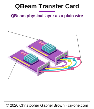
Asset valuation: $7,000,000,000. Project 76 · cri-one.com portfolio · Author: Christopher Gabriel Brown Quantum PHY is a PCIe host bus adapter that uses the patented QBeam physical layer as a plain wire — moving classical bytes (files, RDMA payloads, NVMe-oF, model weights, ledger writes) between e
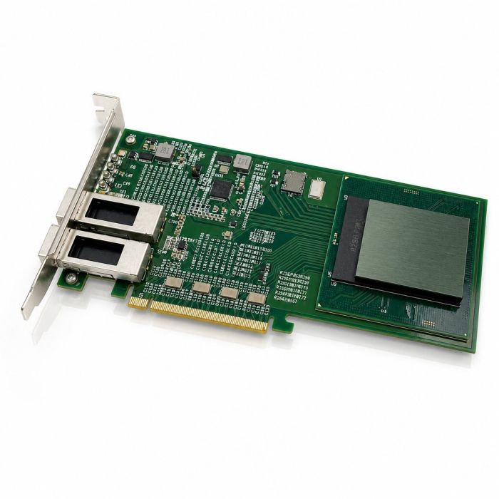
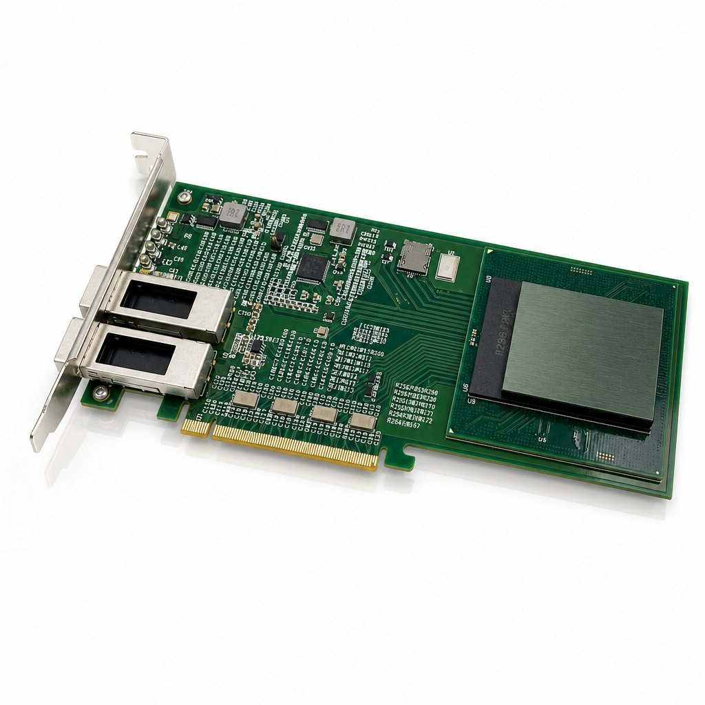
Imagine the link between your accelerator boards being a card you slide into an ordinary PCIe slot, with four QBeam lanes on the bracket. That is the Quantum PHY QBeam Transfer Card. QBeam was filed as a wireless quantum send-and-receive layer, and this card runs it in classical mode, as a plain wire: files, RDMA payloads, NVMe-oF, model weights and ledger writes move between AutoPhi boards in the same chassis, rack or row. No qubits go on the wire and nothing is teleported. The card borrows QBeam for what it does well with ordinary bytes. It stays operable from minus 40 to plus 85 degrees Celsius without active cooling, it absorbs lane-to-lane board skew without retraining, and it fits four lanes on a single-slot half-height bracket. The design target is 400 GB/s in both directions with a 400 ns cut-through budget from one host's doorbell to the other host's memory, and the host sees one PCIe function carrying 64 virtual functions.
This is for datacenter operators and the engineering buyers who build their fabric. The line is thirteen SKUs: twelve silicon generations from 7 nm to 2 nm, each with its own foundry hand-off, plus the reference board. On file are the full spec, bill of materials, 12-layer stackup, wire protocol, driver ABI, RTL scaffolding, link firmware in C, a host daemon in Rust and an SDK in C, Python and Rust. The buyer takes a foundry-ready package to a contract manufacturer for schematic capture, layout, fab, bring-up and compliance; the filed patent stays with the inventor.
Description
76 — Quantum PHY QBeam Transfer Card (SKU 2107)
SKU: 2107 | Product slug: 76-qbeam-transfer | Categories: Quantum PHY, AutoPhi Boards / Interconnect / Silicon | Inventor: Christopher Gabriel Brown
Patent dependency (filed, non-provisional utility, pro se): USPTO Application 19/722,805 — INTEGRATED WIRELESS DATACENTER FABRIC WITH PHASED-ARRAY COOLING ANTENNA, ORDER-PRESERVING ANTENNA SERIES, AND QUANTUM-TELEPORTATION PROTOCOL ATOP A SHARED CLASSICAL CHANNEL (ExitPhi). Filed 2026-06-27 4:14:28 PM ET. 30 claims. Confirmation 4017. Patent Center 77974071. Canonical source for QBeam, CoolBeam, and PipeBeam technologies used in this card. Additional normative reference: USPTO Application 19/717,706 (UniPhi Retroactive Wireless Adapter, filed 2026-06-24) — endpoint adapter framing reference.
Status: Foundry-ready (L4). Full SPEC + BOM + 12-layer STACKUP + wire-protocol specification + host-driver ABI contract on file. Physical-design flow output present for all 12 silicon generations (APM01-D-QPHY through APM12-D-QPHY). Each generation ships a canonical 44-line FOUNDRY_HANDOFF.md. QBeam is a filed non-provisional USPTO utility patent. Patent alignment verified against ExitPhi patent text. ASIC RTL scaffolding, link firmware (C), host daemon scaffolding (Rust), and SDK source (C + Python + Rust) included. Reference-board BOM drafted to hand off to a contract manufacturer for schematic capture and layout. KiCad schematic capture, PCB layout, Gerber generation, prototype fab, bring-up, PCIe 5.0 PCI-SIG compliance, FIPS 140-3 crypto-module certification, and interop testing against AutoPhi endpoint boards are buyer/CM/cert-lab scope.
Overview
The Quantum PHY QBeam Transfer Card is a single PCIe 5.0 x16 half-height half-length (HHHL) host bus adapter (HBA) that presents the patented QBeam physical layer as a plain byte-oriented fabric interface. The card carries classical payloads only — files, RDMA, NVMe-oF, model weights, ledger writes, and control traffic — between AutoPhi accelerator boards housed in the same chassis, rack, or row. No qubits are placed on the wire. No teleportation is performed. The QBeam PHY silicon is reused for its classical-modulation properties (density, thermal integrity, cable-freeness) and nothing else.
The card sits in a standard PCIe 5.0 x16 slot. On the bracket side it exposes four QBeam lanes in SFF-8674 cages; on the host side it enumerates as a single PCIe function with SR-IOV support for up to 64 virtual functions . Design-target aggregate bandwidth is 400 GB/s bidirectional (4 lanes × 100 GB/s per lane) with a 400 ns cut-through latency budget from Host A doorbell write to Host B DMA write.
The product line comprises 13 purchasable SKUs : 12 silicon configurations (APM01-D-QPHY through APM12-D-QPHY, one per AutoPhi Modern generation, spanning 7 nm to 2 nm) plus the umbrella reference HBA board design. The reference HBA ships with the APM07-D-QPHY (3 nm, IFS 18A) as the mid-generation shipping baseline; any variant APM04 through APM12 drops in mechanically compatible.
Scientific Basis
The QBeam physical layer, invented and filed as part of the ExitPhi patent application (USPTO App# 19/722,805), was originally shown to modulate a quantum carrier for wireless quantum-to-quantum teleportation. Two invariants of the invention — CoolBeam thermal integrity and PipeBeam temporal alignment — are carrier-agnostic . When the classical-mode strap on the qbeam_lane macro is asserted, the analog front-end delivers a byte-oriented modulation with three measurable properties superior to copper-serdes or optical-fiber alternatives:
Property QBeam Classical-Mode Advantage Conventional Alternative
Thermal envelope Operable −40 °C to +85 °C without active cooling (CoolBeam) Copper-serdes PHYs in the same PCIe CEM 5.0 slot budget typically require active cooling above +55 °C ambient
Length-mismatch tolerance PipeBeam re-aligner absorbs ±8 mil PCB skew across parallel lanes without lane-to-lane retraining Optical alternatives are more tolerant but at 10× cost
Cable-free density 4 lanes on a single-slot HHHL bracket, each carrying 100 GB/s (design target) Comparable InfiniBand HBA requires 4× QSFP-DD or 8× QSFP+ cages
System Context
The card connects AutoPhi accelerator boards (PCIe5-256, BGA256, PCIe5-1536, and related V19 catalog SKUs) across a QBeam fabric. Each host runs Linux or Windows. The fabric is defined as the collection of Quantum PHY HBAs plus the QBeam wire runs connecting them. Routing is fabric-local; each HBA knows its own Local Identifier (LID) and the peer LIDs on each of its 4 QBeam ports.
Bracket contents 4× SFF-8674 QBeam cages (J1–J4), 4× bicolor green/red bracket status LEDs (LED1–LED4)
Mounting 2 mounting holes (MH1–MH2) per CEM 5.0 §3.4
Heatsink Custom passive aluminium heatsink (HS1), 35×35×15 mm fin, with 3 W/mK thermal interface material (PAD1, 0.5 mm)
Custom bracket Single-slot HHHL bracket (BR1) with LED windows + SFF-8674 pass-through
Interrupt model MSI-X: 32 vectors on PF, 4 per VF. Coalescing: 0–255 completions or 0–65,535 µs. Poll mode supported.
Protocol name QPHY-P1 (inventor-defined; not InfiniBand, RoCE, NVLink, or CXL compatible at the wire level)
Frame format 32-bit header + 16-byte payload prefix + variable payload body (64 B–4,096 B) + 128-bit trailer
Header fields dst_lid (16 bits) + src_lid (16 bits)
Payload prefix fields opcode (1 B), vc (1 B), flags (2 B), seq (4 B), xid (4 B), length (4 B)
Trailer 128-bit AES-256-GCM authentication tag over (header || prefix || body)
FEC Reed-Solomon RS(255, 239) per lane — corrects up to 8 symbol errors per 239 data symbols; block boundary aligned to frame boundaries
Encryption AES-256-GCM at link-layer; per-fabric key provisioned out-of-band via MMIO; nonce = (src_lid || dst_lid || seq) padded to 12 bytes
Key rotation Host-driven atomic KEY_EPOCH control write; drain-and-switch; no frames encrypted under two keys simultaneously
Flow control Credit-based: 64 credits per virtual channel per direction; 1 credit = 1 frame (any payload size)
Virtual channels 8 VCs, head-of-line independent; VC 0 reserved for control
Sequence numbers 32-bit per-VC per-direction, monotonically increasing; no wrap at 400 GB/s for ~112 hours
The APM01-D-QPHY is a variant of the APM01-D Nexus Core (Data Processing Unit) from the AutoPhi Modern family. The variant swaps the Nexus Core’s baseline 2× 400 GbE MACs for 4× QBeam classical-mode PHY lanes , adds a PCIe 5.0 x16 endpoint , and upgrades the AES-256-GCM crypto engine to per-lane parallel. All other Nexus Core features are retained: 8 Light Trigger cores, 32 programmable packet processors, hardware compression (LZ4, Zstd), regex/pattern-matching engine, NVMe-oF target/initiator (32 queues), RAID/erasure-coding engine, RDMA (RoCEv2-shim) queue pairs, and a 512-neuron anomaly-detection co-processor.
No third-party ISA licenses. American Made. Nine Ultimate Technologies present per AutoPhi Modern family contract.
SKU Gen Process Foundry Die Side (mm) Thickness (mm) Active Layers Peak GB/s (Design Target) Fade vs APM01
APM07-D-QPHY (bold) is the shipping baseline of the reference HBA. Package: FCBGA-1024, 35×35 mm. Any variant APM04 through APM12 drops in mechanically compatible. Package families across the line: QFN-56 (single-lane variant), BGA-324 (dual-lane variant), FCBGA-1024 (flagship 4-lane variant).
U1 1 APM07-D-QPHY [custom] FCBGA-1024, 35×35 mm Intel Foundry Services (IFS 18A) Link controller: 4× QBeam PHY + MAC + DMA + PCIe5 x16 EP + AES-GCM
Power source: Slot-only (12 V + 3.3 V from the PCIe slot). No external power connector. Total board dissipation: 42 W typical, 68 W max (within the 75 W CEM 5.0 slot budget). U1 core dissipation: 38 W typical.
SW1 1 Omron B3W-4155 THT Recovery / factory-reset button (protrudes through bracket cutout)
Total thickness: 1.60 mm (±10%). Material: FR-4 Tg170, halogen-free. Surface finish: ENIG (0.05 µm Au over 3 µm Ni min). Solder mask: LPI green, both sides. Silkscreen: white epoxy, both sides. Flammability: UL 94V-0. Manufacturing class: IPC-6012 Class 6 (signal layers), IPC-A-600 Class 3 (finished appearance).
0x000C 4 QPHY_STATUS R bit 0 = ready, bits 1–4 = per-lane link, bit 5 = key loaded, bit 6 = fabric joined
0x0010 4 QPHY_CTRL W bit 0 = enable, bit 1 = FLR, bit 2 = link-retrain, bits 3–6 = per-lane reset
0x0040 64 QPHY_LANE_STATUS R 16 bytes × 4 lanes: FEC corrects, uncorrectable, retrain count, LOS count
0x0400 512 QPHY_VC_CFG R/W 8 VCs × 64 bytes: credit window, priority, backpressure threshold
PHY-only reset Cycles a single QBeam lane for debug; other three lanes stay up in degraded mode
PipeBeam misalignment Aligner RX Automatic re-align; if 3 consecutive attempts fail, link retrain
The on-chip firmware (running on Light Trigger cores) implements a 10-state link state machine:
DEGRADED One or more lanes lost; data path operational on remaining lanes; retrain attempted
Linux Upstream-style character device ( /dev/qphy0 ) + libqphy userspace shim + optional ib_qphy module (Verbs/RDMA provider). Debug via /sys/class/qphy/qphyN/lane_status , /sys/class/qphy/qphyN/counters , /sys/class/qphy/qphyN/event_ring .
Windows WDM driver with SR-IOV support; exposes raw fabric API + NDIS shim for RDMA-capable NIC presentation. Device path: \\.\qphyN .
Driver Bring-Up Sequence
- PCIe enumeration; BARs mapped.
- Read QPHY_ID , QPHY_VER , QPHY_CFG_ID . Refuse to attach if magic wrong or version incompatible.
- Write QPHY_CTRL.enable = 1 . Wait for QPHY_STATUS.ready = 1 .
- Register with the qphyd daemon; receive LID assignment.
- Write QPHY_LID and QPHY_KEY ; assert QPHY_STATUS.key_loaded and .fabric_joined .
- Configure QPHY_VC_CFG per operator policy.
- Allocate SQ/CQ memory; program per-queue MMIO windows (BAR 4).
- Enable MSI-X vectors.
- Driver ready; expose /dev/qphyN and (optional) ib_qphy verbs provider.
C SDK ( sdk/c/ ) C11 Reference libqphy client. One header ( qphy_sdk.h ) + sources. Builds as libqphy.so (shared library). API: qphy_open , qphy_close , qphy_queue_create , qphy_queue_destroy , qphy_submit , qphy_poll , qphy_wait , qphy_rdma_write , qphy_rdma_read , qphy_get_counters , qphy_strerror . SDK version: 0.1.0.
Python bindings ( sdk/python/qphy/ ) Python pip-installable wrapper over the C SDK via cffi.
Rust crate ( sdk/rust/ ) Rust Idiomatic Rust bindings, no_std friendly for embedded hosts.
Link firmware ( firmware/link/ ) C11 (bare-metal) APM01-D-QPHY Light Trigger cores Link-layer state machine: PHY bring-up, RS-FEC lock, PipeBeam alignment, credit accounting, doorbell dispatch, MSI-X delivery. Cross-compiles via autophi-lightrigger-gcc (on-chip target) or gcc (POSIX host simulator). No libc, no dynamic allocation, no float. Build: make TARGET=on-chip or make TARGET=host-sim .
Host daemon ( firmware/host/ ) Rust Host OS (Linux/Windows) Fabric discovery, LID assignment, virtual-channel policy, per-tenant metering, telemetry export to operator observability stack. Communicates with link firmware via MMIO registers.
Path A — Open Source (OpenLANE) APM01, APM02 evaluation builds on SkyWater sky130 Yosys (synthesis), OpenROAD (P&R), Magic (DRC/GDSII), Netgen (LVS) GDSII, LEF, DEF, gate-level netlist; submit to SkyWater MPW/shuttle
Path B — Commercial (Synopsys / IFS) APM03–APM12 production builds Synopsys Design Compiler (synthesis), IC Compiler II (P&R), Mentor Calibre (DRC/LVS/ERC) GDSII, foundry-signoff netlist; submit to IFS production tape-out
APM03 runs both flows for cross-validation: sky130 evaluation build feeds an IFS N7-equivalent risk build before production.
Formal verification Protocol-conformance proof for MAC flow control (LTL: “no credit is ever spent twice”); AES-GCM tag-verification safety property —
Continuous integration OpenLANE regression on APM01/02 sky130 build in CI —
Facility ceiling (dragonfly-of-dragonflies) >256 5 hops Alternate routing; partition-resistant
Beyond one facility, the recommended product is AeroPhi (Project 55) with its six-tier fractal mesh.
I²C sideband J5 header (2.54 mm 5-pin, board edge, unpopulated by default). On-board BMC (U2) or host BMC via slot sideband can read link status, temperature, and error counters without touching PCIe.
JTAG J6 header (2.54 mm 10-pin, board edge, unpopulated by default).
Recovery button SW1 (tactile, Omron B3W-4155, board edge, protrudes through bracket cutout).
Host-side debug (Linux) /sys/class/qphy/qphyN/lane_status , /sys/class/qphy/qphyN/counters , /sys/class/qphy/qphyN/event_ring (read-only ring dump, drain-on-read). qphyd local Unix socket for topology dumps and per-VF metering.
Reference-Board Bring-Up Plan
- Power-only bring-up: Populate power stage only; verify all rails come up in sequence.
- Boot-flash bring-up: Load APM01-D-QPHY boot ROM into U3 (SPI flash); apply PERST# release; verify UART banner.
- PCIe link-training: Insert into a compliance host; verify Gen5 x16 link at PCIe LTSSM L0.
- PHY loopback: Cable J1↔J2; run BIST; verify BER Peer link: Cable to a second HBA; verify LINK_HELLO / LINK_ACK exchange, credit grant, traffic loopback.
- Compliance: Submit to PCI-SIG for Gen5 compliance workshop.
ExitPhi IC 54 The ExitPhi patent itself, sold as an IP wrap with the WFA silicon family (WFA-Node / WFA-Hub / WFA-Mesh)
AeroPhi 55 Six-tier fractal mesh consumer of QBeam; T1–T6 board reference designs; 20 silicon configurations
QPHY PCIe Card 77 Cable-free PCIe add-in card hosting a QBeam-enabled chip; antenna handles chip-to-chip wirelessly; PCIe fingers handle only host↔chip
Source, RTL, revenue, and contracts do not co-mingle across families. Each buyer signs their own LICENSE with the inventor.
US Export Configurations at 5 nm and below subject to US EAR / BIS export controls; buyer responsible for compliance
DFARS 252.204-7012 IFS handles under standard DFARS trusted-foundry framework; buyer’s tape-out contract inherits
America First restriction License permits deployment only in the USA; foundries outside the USA (e.g. TSMC N7 secondary) require inventor written consent case-by-case
U1 (APM07-D-QPHY) cost is inventor-set and included in the finished-card list price. Sample lead time from tape-out: 20 weeks; production lead time: 26 weeks.
Trademarks
The following marks are used but not registered as of this document’s date: “Quantum PHY,” “QPHY,” “QBeam,” “CoolBeam,” “PipeBeam,” “ExitPhi,” “AeroPhi,” “AutoPhi,” “cri-one.” “QPHY” is a downstream product name coined at cri-one.com; the canonical patent term is “QBeam.”
SPEC.md Top-level technical specification: scope, system context, wire protocol summary, hardware families, firmware families, host driver, SDK families, deliverables, deferred items, revision history
IP_REFERENCES.md Filed IP dependency chain, product-name derivation trail, sibling product families, trademark list
docs/ARCHITECTURE.md On-card block diagram, TX/RX data paths, boot path, control path, reset domains, failure modes, thermal design
docs/QPHY_PROTOCOL.md Full QPHY-P1 wire protocol: frame format, header/prefix/trailer fields, FEC, encryption, flow control, virtual channels, sequence numbers, ordering, control opcodes, encoding
docs/HOST_DRIVER_CONTRACT.md Host driver ABI: PCIe enumeration (Vendor/Device/Class IDs), BAR layout, register map, queue-pair model, SQE/CQE formats, error codes, interrupt model, driver bring-up sequence, suspend/resume, debug interfaces
docs/FABRIC_TOPOLOGIES.md Fabric topology catalog: point-to-point, star, ring, 2D torus, dragonfly, facility ceiling; wiring costs, failure envelopes, wiring-bill generator placeholders
hardware/QPHY_HBA_BOARD/SPEC.md Reference PCIe HBA board specification: mechanical, silicon, power rails, clocks, QBeam bracket ports, sideband, passives, DFM constraints, DRC, bring-up plan
hardware/QPHY_HBA_BOARD/BOM.md Full bill of materials: 13 active ICs (U1–U13), ~640+ passives (capacitors, ferrites, resistors, ESD, ORing FETs), clocks (Y1–Y3), connectors (J0–J6), LEDs, bracket, heatsink, TIM, recovery button, with vendors and approximate costs
hardware/QPHY_HBA_BOARD/STACKUP.md 12-layer PCB stackup: layer-by-layer copper weights, dielectric thicknesses, Er values, impedance targets (85 Ω PCIe, 100 Ω QBeam, 50 Ω control), length-match tolerances, via structure, manufacturing class (IPC-6012 Class 6, ENIG, UL 94V-0)
hardware/APM-D-QPHY/SPEC.md APM01-D-QPHY silicon specification: lineage from APM01-D Nexus Core, scientific claim, block diagram, 12-generation configuration table, foundry-ready deliverables, EDA flow (Path A + Path B), verification plan, compatibility with AutoPhi Modern
hardware/APM-D-QPHY/FOUNDRY_STANDARDS.md Foundry-selection matrix for all 12 configurations: primary/secondary foundry, PDK, EDA flow, submission mode, NRE and per-die cost estimates, compliance and export notes
parts/APM01-D-QPHY/ through parts/APM12-D-QPHY/ 12 per-generation directories, each containing: FOUNDRY_HANDOFF.md (44-line canonical AutoPhi handoff), manifest.json (machine-readable per-SKU manifest), STORE_LISTING.md (store copy), store_description.html (live store HTML), synth.sdc (synthesis constraints), floorplan.tcl (die floorplan), pnr_config.tcl (P&R config), openlane_config.json (OpenLANE config for APM01/02 sky130 evaluation)
firmware/link/qphy_link.h Link-layer state machine header: state definitions, event codes, wire opcodes, per-VC credit structures, public API declarations
firmware/link/qphy_link.c Link-layer state machine implementation: bare-metal C, no libc, no dynamic allocation, portable to on-chip and POSIX host simulator
firmware/link/Makefile Build system for link firmware: on-chip ( autophi-lightrigger-gcc ) and host-sim ( gcc ) targets
firmware/host/ Host-side daemon scaffolding (Rust): fabric discovery, LID assignment, VC policy, metering, telemetry
sdk/c/qphy_sdk.h C SDK header: opaque handles, error codes, SQE/CQE structures, card discovery, queue-pair management, submit/poll/wait, RDMA convenience, telemetry counters
sdk/c/qphy_sdk.c C SDK reference implementation: Linux ( /dev/qphyN ) and Windows ( \\.\qphyN ) device access, doorbell ringing, CQ polling, RDMA write/read
figures/apm01-d-qphy.png through figures/apm12-d-qphy.png 12 per-generation silicon product images
Deferred / Open Items (Buyer or CM Scope)
- Silicon tape-out of any QPHY configuration through the AutoPhi Day-One production stack
- KiCad schematic capture (buyer/CM scope; the inventor package delivers SPEC + BOM + STACKUP)
- PCB layout and Gerber generation (buyer/CM scope)
- Prototype fab and bring-up
- PCIe 5.0 compliance passes at PCI-SIG
- FIPS 140-3 certification for the crypto module
- Interop tests against AutoPhi PCIe5-256, BGA256, and PCIe5-1536 endpoint boards
How this is delivered
This package ships on a single Blu-ray disc, posted to the delivery address on your order. The archive on the disc is AES-256 encrypted; the passphrase is sent separately, by email, once the disc is despatched — so the disc alone is of no use to anyone who intercepts it.
Discs are despatched by tracked, signed-for post. Allow 5 business days for mastering and verification before despatch.
© 2026 Christopher Gabriel Brown. All rights reserved.
Photo
Footnotes
- Product number 8526.
- Family: qbeam.
- Purchase: When you buy, you buy the use of that blueprint only.