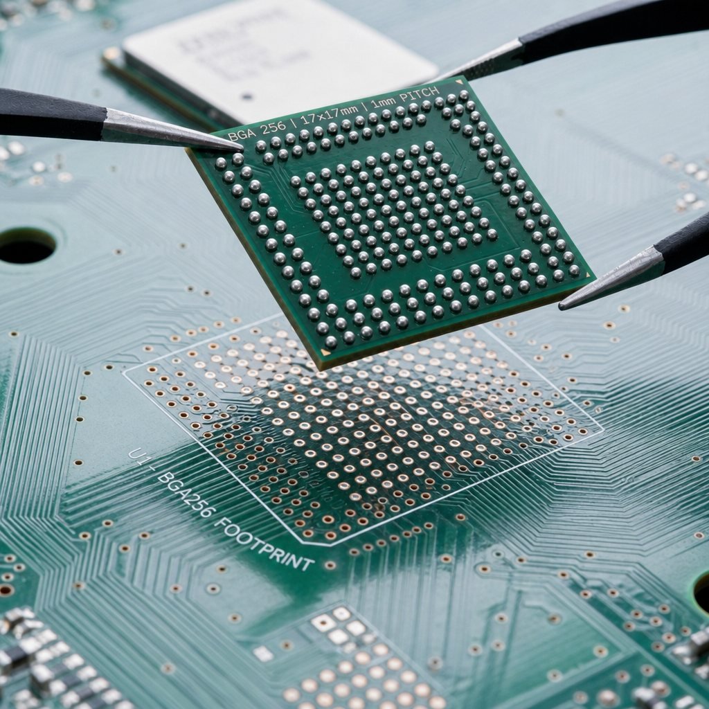
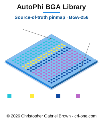
40-autophi-bga256

$99,999,999.00
In stock
SKU
2069
Asset valuation: $16,000,000,000. Last edited: 2026-04-27 Dedicated source-of-truth project for AutoPhi BGA component definitions. This project owns: - BGA footprints (libs/footprints) - BGA symbols (libs/symbols) - BGA pinmaps (pinmaps) - Repeatable generation scripts (scripts)

Valuation

Generous asset valuation: $16,000,000,000. The listed price is the platform maximum; acquisition at valuation is handled by direct enquiry.

40-autophi-bga

40-autophi-bga

Last edited: 2026-04-27

Dedicated source-of-truth project for AutoPhi BGA component definitions.

This project owns:

  • BGA footprints (libs/footprints)
  • BGA symbols (libs/symbols)
  • BGA pinmaps (pinmaps)
  • Repeatable generation scripts (scripts)

Board projects (for example 35-autophi-quantum-pcie5 and 39-autophi-pcie5)

should consume artifacts from here, not define BGA data ad hoc.

Current mechanical planning envelope for BGA interchange is up to 95 mm

based on latest board mechanical clearance updates.

Current Seed Artifacts

  • Footprint: libs/footprints/AutoPhi.pretty/BGA-256_20x20mm_P1.0mm.kicad_mod
  • Seeded from 39-autophi-pcie5
  • Pinmap template: pinmaps/AUTOPHI_BGA256_pinmap_template.csv
  • Generated from the footprint pads (256 balls)
  • Large-package scaffold:
  • Footprint: libs/footprints/AutoPhi.pretty/BGA-1536_95x90mm_P2.0mm.kicad_mod
  • Pinmaps:
  • pinmaps/AUTOPHI_BGA1536_pinmap_template.csv
  • pinmaps/AUTOPHI_BGA1536_pinmap_working.csv
  • Symbol: libs/symbols/AutoPhi_BGA1536_working.kicad_sym

Commands

Profile switch defaults are now supported in geometry-seeding scripts:

v19_default, zetta_ref, smd15_ref. Use --profile to select a

dimension/default set and only override fields when needed.

Generate/rebuild the pinmap template from the footprint:

python scripts/generate_bga_pinmap_template.py `
  --footprint "d:\special\40-autophi-bga\libs\footprints\AutoPhi.pretty\BGA-256_20x20mm_P1.0mm.kicad_mod" `
  --out "d:\special\40-autophi-bga\pinmaps\AUTOPHI_BGA256_pinmap_template.csv" `
  --part AUTOPHI_BGA256

Generate a new parametric large BGA footprint (example: 1536 pins):

python scripts/generate_bga_footprint_grid.py `
  --out "d:\special\40-autophi-bga\libs\footprints\AutoPhi.pretty\BGA-1536_95x90mm_P2.0mm.kicad_mod" `
  --name "BGA-1536_95x90mm_P2.0mm" `
  --profile v19_default

For non-default profiles, if row/column/pitch are not canonically defined yet,

provide them explicitly:

python scripts/generate_bga_footprint_grid.py `
  --out "d:\special\40-autophi-bga\libs\footprints\AutoPhi.pretty\ZETTA_REF.kicad_mod" `
  --profile zetta_ref `
  --rows 32 `
  --cols 48 `
  --pitch 2.0

Initialize a working pinmap from a template:

python scripts/initialize_pinmap_working.py `
  --in "d:\special\40-autophi-bga\pinmaps\AUTOPHI_BGA1536_pinmap_template.csv" `
  --out "d:\special\40-autophi-bga\pinmaps\AUTOPHI_BGA1536_pinmap_working.csv" `
  --profile v19_default

Seed domains on all rows for large BGAs and promote canonical names:

python scripts/seed_ab_domains.py `
  --rows "ALL" `
  --seed-tag "domain-seed-v1" `
  --pinmap "d:\special\40-autophi-bga\pinmaps\AUTOPHI_BGA1536_pinmap_working.csv"

python scripts/promote_provisional_signals.py `
  --pinmap "d:\special\40-autophi-bga\pinmaps\AUTOPHI_BGA1536_pinmap_working.csv" `
  --tag "canonical-name-seed-v1"

Generate/rebuild a KiCad symbol library from the pinmap:

python scripts/generate_bga_symbol_from_pinmap.py `
  --pinmap "d:\special\40-autophi-bga\pinmaps\AUTOPHI_BGA256_pinmap_template.csv" `
  --out "d:\special\40-autophi-bga\libs\symbols\AutoPhi_BGA.kicad_sym" `
  --symbol AUTOPHI_BGA256 `
  --reference U `
  --value AUTOPHI_BGA256 `
  --footprint "AutoPhi:BGA-256_20x20mm_P1.0mm"

Normalize noisy placeholders and create a working pinmap:

python scripts/normalize_pinmap_placeholders.py `
  --in "d:\special\40-autophi-bga\pinmaps\AUTOPHI_BGA256_pinmap_starter.csv" `
  --out "d:\special\40-autophi-bga\pinmaps\AUTOPHI_BGA256_pinmap_working.csv"

Create a row-focused workset (example: rows A+B) and report completion:

python scripts/make_pinmap_workset.py `
  --pinmap "d:\special\40-autophi-bga\pinmaps\AUTOPHI_BGA256_pinmap_working.csv" `
  --rows A,B `
  --out "d:\special\40-autophi-bga\pinmaps\worksets\AUTOPHI_BGA256_rows_A_B.csv"

python scripts/pinmap_completion_report.py `
  --pinmap "d:\special\40-autophi-bga\pinmaps\AUTOPHI_BGA256_pinmap_working.csv"

Seed provisional canonical domains for selected rows and regenerate symbol:

python scripts/seed_ab_domains.py `
  --rows "A,B,C,D,E,F" `
  --seed-tag "domain-seed-v1" `
  --pinmap "d:\special\40-autophi-bga\pinmaps\worksets\AUTOPHI_BGA256_rows_A_B.csv" `
  --pinmap "d:\special\40-autophi-bga\pinmaps\AUTOPHI_BGA256_pinmap_working.csv"

python scripts/generate_bga_symbol_from_pinmap.py `
  --pinmap "d:\special\40-autophi-bga\pinmaps\AUTOPHI_BGA256_pinmap_working.csv" `
  --out "d:\special\40-autophi-bga\libs\symbols\AutoPhi_BGA_working.kicad_sym" `
  --symbol "AUTOPHI_BGA256" `
  --reference "U" `
  --value "AUTOPHI_BGA256" `
  --footprint "AutoPhi:BGA-256_20x20mm_P1.0mm"

One-command reproducible rebuild (normalization + seeding + symbol + report + checkpoint):

powershell -ExecutionPolicy Bypass -File .\scripts\rebuild_provisional_seed.ps1 `
  -Rows "A,B,C,D,E,F,G,H,J,K,L,M,N,P,R,T" `
  -SeedTag "domain-seed-v1"

Promote provisional MGMT/HSIO placeholder names to stable canonical names:

python scripts/promote_provisional_signals.py `
  --pinmap "d:\special\40-autophi-bga\pinmaps\AUTOPHI_BGA256_pinmap_working.csv" `
  --tag "canonical-name-seed-v1"

Finalize voltage-domain placeholders and normalize duplicate note tags:

python scripts/finalize_power_rails.py `
  --pinmap "d:\special\40-autophi-bga\pinmaps\AUTOPHI_BGA256_pinmap_working.csv" `
  --pinmap "d:\special\40-autophi-bga\pinmaps\AUTOPHI_BGA1536_pinmap_working.csv" `
  --tag "power-domain-normalize-v1"

python scripts/normalize_pinmap_notes.py `
  --pinmap "d:\special\40-autophi-bga\pinmaps\AUTOPHI_BGA256_pinmap_working.csv" `
  --pinmap "d:\special\40-autophi-bga\pinmaps\AUTOPHI_BGA1536_pinmap_working.csv"

Validate pinmap/symbol/footprint alignment:

python scripts/validate_bga_library.py `
  --entry "d:\special\40-autophi-bga\pinmaps\AUTOPHI_BGA256_pinmap_working.csv,d:\special\40-autophi-bga\libs\symbols\AutoPhi_BGA_working.kicad_sym,d:\special\40-autophi-bga\libs\footprints\AutoPhi.pretty\BGA-256_20x20mm_P1.0mm.kicad_mod,AutoPhi:BGA-256_20x20mm_P1.0mm" `
  --entry "d:\special\40-autophi-bga\pinmaps\AUTOPHI_BGA1536_pinmap_working.csv,d:\special\40-autophi-bga\libs\symbols\AutoPhi_BGA1536_working.kicad_sym,d:\special\40-autophi-bga\libs\footprints\AutoPhi.pretty\BGA-1536_95x90mm_P2.0mm.kicad_mod,AutoPhi:BGA-1536_95x90mm_P2.0mm"

Build consolidated Magento draft CSV (34 board rows + BGA library rows):

python scripts/build_magento_series_draft.py

Output:

  • exports/magento_import_series_draft.csv

Seeding history and rationale:

  • docs/PINMAP_SEEDING_LOG.md
  • docs/BGA_CATALOG.md
  • docs/CANONICAL_DIMENSIONS_MATRIX.md
  • docs/LIBRARY_GOVERNANCE.md
  • docs/RELEASE_V1.md
  • docs/POWER_POLICY.md
  • docs/BOARD_SERIES_STATUS.md

Next Steps

1. Fill signal/bank/voltage_domain/direction in the pinmap CSV.

2. Generate a production KiCad symbol from that pinmap.

3. Version the symbol + footprint as reusable library releases.

4. Point 35 and 39 at this library.

40 - Autophi Bga256

40 - Autophi Bga256

> Internal playbook -- not for public eyes.

> Last scaffolded: 2026-05-11

1. Identity

2. One-liner

> - Footprint: libs/footprints/AutoPhi.pretty/BGA-256_20x20mm_P1.0mm.kicad_mod - Seeded from 39-autophi-pcie5 - Pinmap template: pinmaps/AUTOPHI_BGA256_pinmap_template.csv - Generated from the footprint pads (256 balls) - Large-package scaffold: - Footprint: libs/footprints/AutoPhi.pretty/BGA-1536_95x90mm_P2.0mm.kicad_mod - Pinmaps: -...

*(Edit this once. It becomes the single sentence you reuse in replies,

on the catalog page, and at the top of any future write-up.)*

3. What's actually in the folder

  • docs/ (9 entries)
  • exports/ (1 entries)
  • libs/ (2 entries)
  • output/ (0 entries)
  • pinmaps/ (13 entries)
  • sales-pitches/ (3 entries)
  • scripts/ (17 entries)
  • sources/ (3 entries)
  • CHANGELOG.md
  • CONTACT_INFO.txt
  • MANIFEST.json
  • PLAYBOOK.md
  • README.md

4. README at a glance

Top sections found in README.md:

  • Current Seed Artifacts
  • Commands
  • Next Steps

(Full text: D:\special\40-autophi-bga256\README.md)

5. Hook lines (pick the one that fits the reader)

  • (default) - Footprint: libs/footprints/AutoPhi.pretty/BGA-256_20x20mm_P1.0mm.kicad_mod - Seeded from 39-autophi-pcie5 - Pinmap template: pinmaps/AUTOPHI_BGA256_pinmap_template.csv - Generated from the footprint pads (256 balls) - Large-package scaffold: - Footprint: libs/footprints/AutoPhi.pretty/BGA-1536_95x90mm_P2.0mm.kicad_mod - Pinmaps: -...
  • (skeptic / 'what is this really?') TODO -- one honest sentence about

what's solved here that wasn't before.

  • (buyer's-finance angle) TODO -- pricing/risk framing (zero-upfront,

4-step credit-forward, revenue share if applicable).

  • (competitor question) TODO -- the one comparable product or approach

this most often gets confused with, and the one-sentence delta.

6. Reply patterns

When inbound lands, fall back to the cross-portfolio patterns in

D:\special\manager\emails\PLAYBOOK_software_for_data.md (sections 5

and 8 are reusable across every project) and adapt the specifics.

The product-specific bits to fill in here (TODO):

  • One objection unique to this project + the honest answer
  • One pricing anchor unique to this project
  • One reason to walk away that's worth saying out loud

7. Status & gaps

  • Vault: EMPTY -- no archive (must create before 'Send Vault' works)
  • Catalog presence: TODO -- search cri-one.com/store for this product

and paste the live URL here.

  • PoF readiness: TODO -- is there a working demo / sample / proof a

prospect could run in under an hour?

  • NDA-gated technical brief: TODO -- written? not written? where?
  • Critical missing piece before this can close: TODO.

8. Quick links

  • Folder: D:\special\40-autophi-bga256\
  • Catalog (cri-one.com): TODO
  • Related projects in portfolio: TODO (cross-reference here once mapped)

*This scaffold was auto-generated. Replace TODOs as you learn each project

better. Search across all playbooks: grep -ri "<term>" D:\special\\PLAYBOOK.md

Prior Art — LED Power Recycling (this project)

Prior Art — LED Power Recycling (this project)

Status: Research only — third-party patents that overlap with this project's claims. NOT owned by Christopher Gabriel Brown.

Canonical doc: ../PRIOR_ART_LED_RECYCLING_QD_BATTERY.md

Scanned: 2026-05-11

Why this file is here

40-autophi-bga256 packages the AutoPhi processor in a BGA256 package and inherits the LED Power Recycling element from the nine-tech AutoPhi architecture.

Most relevant prior art for this project

Defensible angle

The BGA256 package + the integrated nine-tech AutoPhi stack is the patentable target — not the LED-recycle slice taken in isolation.

Final Cookbook — PCIe + DDR3 + Power Tree Schematic Wiring

Final Cookbook — PCIe + DDR3 + Power Tree Schematic Wiring

This is the complete recipe to take what we've built (pre-labeled symbols,

power-rail spec, pin assignment) and turn it into wired schematics, then a

routed PCB.

Time estimate: 2–3 hours of focused KiCad work, both boards combined.

Part A — Sheet 03: PCIe x16 Edge Connector

1. Open autophi-pcie5-qsfp28-optical-256.kicad_pro (or 1536 variant)

2. Open eeschema, navigate to sheet 03_pcie_x16_edge_connector.kicad_sch

3. Delete the J1 2-pin placeholder (or keep it if it has a different purpose)

4. Place symbol from library: PCIe_x16:PCIe_x16

  • Set reference to J5 (matches existing PCB)

5. Place a GND power symbol below the symbol; connect all GND pins to it

6. Place a +12V power symbol; connect to all +12V pins

7. Place a +3.3V power symbol; connect to all +3.3V and +3.3V_AUX pins

8. Add hierarchical labels (Place → Hierarchical Label) for each PCIe lane:

  • All PETp0..PETp15, PETn0..PETn15, PERp0..PERp15, PERn0..PERn15
  • Plus REFCLK+, REFCLK-, PERST#, WAKE#, CLKREQ#, SMCLK, SMDAT,

PRSNT1#, PRSNT2#, TRST#

9. Wire each pin → corresponding hierarchical label

10. Save

Tip: Pin names already match net names because we updated the symbol —

KiCad's "default net = pin name" feature means you only need to add hierarchical

labels for cross-sheet routing, not local labels.

Part B — Sheet 02: PCIe Retimers

For each of U3, U6, U17, U21 (existing autophi:Ux symbols):

1. Find each retimer instance in the sheet

2. Add hierarchical labels around it for each lane group:

  • U3 → labels for PETp0..3, PERp0..3, etc. (lanes 0-3)
  • U6 → lanes 4-7 (PETp4..7, PERp4..7, etc.)
  • U17 → lanes 8-11
  • U21 → lanes 12-15

3. Wire INA pins to PERp/PERn labels

4. Wire INB pins to PETp/PETn labels

5. Wire OUTA pins to PETp_C/PETn_C labels

6. Wire OUTB pins to PERp_C/PERn_C labels

7. Wire VDD/VIN pins to +3.3V power symbol

8. Wire SCL/SDA to hierarchical labels SMCLK, SMDAT

9. Wire READ_EN, ALL_DONE, ENSMB, PWDN to DS_READ_EN, DS_ALL_DONE,

DS_EN_SMB, DS_PWDN_N hierarchical labels

10. Wire AD0..AD3, RESERVED1..3, VERIFY_PACKAGE, RXDET, EQA to GND power symbol

11. Save

Part C — Sheet 01: Central Processor (BGA)

The BGA U16 has 256 (or 1536) pins. Most already have meaningful net names from

the pinmap. You only need to:

1. Place the BGA symbol if not already placed: AutoPhi_BGA_40:AUTOPHI_BGA256

2. Add hierarchical labels matching what we added in sheets 02/03:

  • On HSIO pairs 0-15: PETp0..PETp15 / PETn0..PETn15 (BGA TX → retimer INB)
  • On HSIO pairs 16-31: PERp0_C..PERp15_C / PERn0_C..PERn15_C (BGA RX ← retimer OUTB)
  • On MGMT_GPIO_00, _01: SMDAT, SMCLK
  • On MGMT_GPIO_18, _19: PERST#, WAKE#

3. For DDR3 — add these hierarchical labels to MGMT_GPIO_24..63 per DDR3_PIN_ASSIGNMENT.md:

  • GPIO_24..38: DDR_A0..DDR_A14
  • GPIO_39..41: DDR_BA0..BA2
  • GPIO_42..50: DDR_CK_P/N, DDR_CKE, DDR_CS_N, DDR_RAS_N, DDR_CAS_N, DDR_WE_N, DDR_ODT, DDR_RESET_N
  • GPIO_51..61: DDR_DQ0..DDR_DQ7, DDR_DQS0_P/N, DDR_DM0

4. Save

Part D — New Sheet (or Sheet 04): DDR3 + DDR3 Power

Either add to existing 04_power_tree.kicad_sch or create new sheet 04b_ddr3.kicad_sch.

D1 — Add DDR3 chips

1. Place 1 (BGA-256) or 4 (BGA-1536) instances of DDR3_x16:DDR3_SDRAM_x16

2. Set references: U4 (and U9, U19, U31 if 1536)

3. Wire the shared address/command bus (broadcast all chips):

  • All 4 chips' A0 pin → hierarchical label DDR_A0
  • Same for A1..A14, BA0..BA2, CK_P, CK_N, CKE, CS#, RAS#, CAS#, WE#, ODT, RESET#

4. Wire per-chip data:

  • U4 DQ0..DQ15 → DDR_DQ0..DDR_DQ15
  • U9 DQ0..DQ15 → DDR_DQ16..DDR_DQ31
  • U19 → DDR_DQ32..DDR_DQ47
  • U31 → DDR_DQ48..DDR_DQ63
  • DQS_L/U_P/N similarly per byte

5. Power: VDD, VDDQ → 1V5 power symbol; VSS, VSSQ → GND

6. Reference: VREFCA → VREFCA; VREFDQ → per-chip VREFDQ_U4 etc.

7. ZQ: each chip's ZQ ball → 240 Ω resistor → GND (one per chip)

D2 — Add power rails (per DDR3_POWER_TREE_ADDITIONS.md)

1. Place TPS62133 (or generic buck) symbol — call it U52

  • Wire VIN → +12V, OUT → 1V5
  • Add 2.2 µH inductor + input/output caps + feedback divider

2. Place TPS51200 (or generic VTT regulator) — call it U53

  • Wire VIN/VLDOIN → 1V5, VTT → VTT_DDR, VTTREF → VREFCA
  • Add input/output caps

3. Add VTT termination resistors at the end of the address/command bus:

  • One 40 Ω resistor per net, between net and VTT_DDR
  • Place AFTER the last DDR3 chip in the bus

Part E — Validation

After all edits:

1. Tools → Annotate Schematic (assign reference numbers to any new components)

2. Tools → Electrical Rules Check (ERC)

  • Fix all errors. Common ones:
  • "Pin not connected" — add a NC flag or wire to a label
  • "Conflicting label types" — make sure power vs signal pins use right symbol
  • "Hierarchical sheet pin not connected to label" — add the corresponding label inside the child sheet

3. Tools → Update PCB from Schematic (Tools → Update Symbols from Library first if symbols changed)

  • Review changes; click Update PCB
  • This propagates all your new net assignments to the .kicad_pcb file

Part F — Re-route the PCB

1. In Pcbnew, place the new components (U52, U53, DDR3 chips, the resistors and caps)

  • Or use the AutoPhi Floorplan Assistant plugin — Tools → External Plugins
  • Alternatively: drag them by hand to reasonable positions

2. Tools → External Plugins → AutoPhi Floorplan Assistant → Keepouts — refresh PCIe + MH keepouts (in case board outline shifted)

3. File → Export → Specctra DSN

4. Run FreeRouting v1.6.5 with -Xmx8g (the JAR is at freerouting-v1.6.5.jar in the project folder)

5. File → Import → Specctra Session to bring SES back

6. Press B to fill GND zones

7. Inspect → Design Rules Checker — fix any clearance / unrouted issues

Part G — Length matching (PCIe 5.0 + DDR3)

PCIe 5.0 differential pairs need ±5 mil length match between P/N. DDR3 byte

lanes need similar matching. Use KiCad's interactive router with length tuning:

1. Open the board in pcbnew

2. Route → Single Track / Differential Pair Length Tuning

3. Click on a P trace, the router shows current length and target

4. Click "Length tuning" mode and add meanders to match the longer trace

5. Repeat for all 16 PCIe pairs and all DDR3 byte lanes

KiCad has a per-net-class length match feature: Setup → Net Classes → DDR

set "diff pair gap" and "max length difference" — the tuner will respect those.

Reference docs (already in this folder)

  • SCHEMATIC_WIRING_CHECKLIST.md — exhaustive pin-by-pin tables
  • DDR3_PIN_ASSIGNMENT.md — FPGA pin map for DDR3
  • DDR3_POWER_TREE_ADDITIONS.md — power rail spec
  • This file — execution recipe

When to ask for more help

If during ERC you get hundreds of errors that don't make sense, OR if Update PCB

from Schematic produces unexpected net changes, post the error list and I can

help debug specific issues.

DDR3 → FPGA Pin Assignment

DDR3 → FPGA Pin Assignment

BGA-256: 16-bit DDR3 (only U4 active; U9/U19/U31 unused)

Uses 30 of the 40 free MGMT_GPIO pins (GPIO_24..63), leaving 10 spare.

Address bus (15 lines)

Bank address (3 lines)

Command + control (8 lines)

Data byte 0 (DQ0..DQ7, DQS0, DM0)

Spare (for byte 1 DQ8..15 if you upgrade later, or unused): GPIO_62, GPIO_63

Per-chip cal/sense (single resistor per chip, no FPGA pin):

  • U4_ZQ → 240Ω resistor to GND, on U4 ball J3
  • VREFCA → midpoint divider on 1.5V → 0.75V (board reference)
  • VREFDQ_U4 → midpoint divider for U4 only

BGA-1536: full 64-bit DDR3 (all 4 chips active)

Uses 75 of the 384 free MGMT_GPIO pins. Same address/command bus mapping as

BGA-256 above (GPIO_24..50), then add:

Data bytes 1-7 (additional 56 lines)

Total: GPIO_24..GPIO_137 = 114 pins. 270 spare for future expansion.

DDR3 Power Tree Additions

DDR3 Power Tree Additions

The current power tree (sheet 04_power_tree.kicad_sch) has 12V/3.3V/1.8V/1.0V

LDO/buck rails but lacks the 1.5V and 0.75V rails DDR3 needs. Add these:

Rail 1 — 1V5 for DDR3 VDD/VDDQ

DDR3 SDRAM needs 1.5V ±5% on every chip. With 4 chips × x16, current draw is

roughly 1.5 A continuous, 3 A peak (during refresh / IO transitions).

Suggested part: Texas Instruments TPS62133 (3A, 17V input, synchronous buck)

  • Footprint: VQFN-10 3×3 mm (Package_DFN_QFN:VQFN-10_3x3mm_P0.5mm)
  • Datasheet pinout (RGT package):

Discrete components needed alongside:

Recommended schematic refdes: U52 (next available power IC reference).

Rail 2 — VTT_DDR (0.75V) for command/address termination

DDR3 fly-by topology requires 0.75V termination at the far end of the address

and command bus (and sometimes DQ). Tracks 1.5V at exactly 50%.

Suggested part: Texas Instruments TPS51200 (3A sink/source VTT tracking)

  • Footprint: SOIC-8 EP (Package_SO:SOIC-8-1EP_3.9x4.9mm_P1.27mm_EP2.41x3.3mm)
  • Pinout (D package):

Discrete components:

Recommended schematic refdes: U53.

VTT termination resistors at the far end of the bus (one per addr/cmd line):

  • Value: 40 Ω typical (some designs use 50 Ω)
  • Net: from each addr/cmd net to VTT_DDR
  • Place near the LAST DDR3 chip in the chain (U31 on BGA-1536 design;

U4 on BGA-256 single-chip design)

For 16-bit DDR3 (BGA-256, 1 chip): need ~25 termination resistors.

For 64-bit DDR3 (BGA-1536, 4 chips): need ~25 termination resistors (still

just ONE bank because address/command are shared).

Rail 3 — VREF_DDR (0.75V reference, low current)

VREFCA (command/address reference) and VREFDQ (data reference) on every DDR3

chip need a low-noise 0.75V (=½ VDDQ).

Simplest implementation: resistor divider from 1V5 to GND

  • Two 1 kΩ 0.1% resistors, each chip gets its own divider tap with 0.1 µF cap
  • Or use a single buffered reference (e.g., TPS51200 has a VTTREF pin already)

For our design: tap VTT_DDR_REF (from TPS51200 pin 5) into all VREFCA pins.

For VREFDQ — one per chip — use:

Updated power tree summary

Schematic edit checklist (sheet 04_power_tree.kicad_sch)

1. Add U52 TPS62133 with surrounding inductor + caps + feedback divider per table above

2. Add U53 TPS51200 + caps per table above

3. Add net labels on the output rails: 1V5, VTT_DDR, VTT_DDR_REF, 1V5_PG

4. Wire up enable: tie 1V5_EN to 12V (always-on after 12V comes up) OR to 3_3V_PG (sequenced)

5. Hierarchical labels on the sheet boundary so other sheets can reference 1V5, VTT_DDR, VREFCA

6. In sheet 01_central_processor.kicad_sch: add 1V5 connection to all DDR3 VDD/VDDQ pins, VTT_DDR to termination resistor block, VREFCA/VREFDQ_* to corresponding chip pins

7. In sheet 04_power_tree.kicad_sch or new sheet 04b_ddr3_term.kicad_sch: add the 25 VTT termination resistors at the far end of the address/command bus

After these additions, Annotate → ERC → Update PCB from Schematic will:

  • Add U52, U53, L_DDRBUCK, all caps and resistors as new footprints needing placement
  • Create the new 1V5 and VTT_DDR net classes (assign 0.4mm trace width via Tools → Edit Pre-defined Sizes if needed)

BGA Catalog

BGA Catalog

Canonical BGA catalog for AutoPhi library development.

Placement Constraint (Global)

  • BGA interchange window (max): 95.0 mm
  • Canonical anchor reference:
  • PCB edge left-bottom: (61.100, 114.650) mm
  • BGA center: (141.500, 95.400) mm

This is a placement/interchange rule, not a package body-size definition.

Confirmed Catalog Entries

1. AUTOPHI_BGA256

  • Footprint: libs/footprints/AutoPhi.pretty/BGA-256_20x20mm_P1.0mm.kicad_mod
  • Symbol: libs/symbols/AutoPhi_BGA_working.kicad_sym
  • Pinmaps:
  • pinmaps/AUTOPHI_BGA256_pinmap_template.csv
  • pinmaps/AUTOPHI_BGA256_pinmap_working.csv
  • Status: in active canonicalization flow

2. AUTOPHI_BGA1536 (large-package class scaffold)

  • Target package envelope: ~90-95 mm body (mechanical window update)
  • Seed footprint: libs/footprints/AutoPhi.pretty/BGA-1536_95x90mm_P2.0mm.kicad_mod
  • Seed symbol: libs/symbols/AutoPhi_BGA1536_working.kicad_sym
  • Seed pinmaps:
  • pinmaps/AUTOPHI_BGA1536_pinmap_template.csv
  • pinmaps/AUTOPHI_BGA1536_pinmap_working.csv
  • Motivation: V19-Pinnacle class package planning
  • Status: scaffolded; pin assignment pending

3. AUTOPHI_BGA576 / AUTOPHI_BGA900 / AUTOPHI_BGA1156 (intermediate ladder)

  • Motivation: the family stepped 256 -> 1536 with nothing between, a 6x jump.

Eleven body variants existed but only two ball counts, so a design needing

~600-1100 I/O had to take a package with far more balls and area than it used.

  • Within the canonical range: CANONICAL_DIMENSIONS_MATRIX.md gives the V19

Pinnacle baseline as 32 mm width, 384..1536 pins across SKUs.

  • Footprints:
  • libs/footprints/AutoPhi.pretty/BGA-576_32x32mm_P1.27mm.kicad_mod
  • libs/footprints/AutoPhi.pretty/BGA-900_32x32mm_P1.0mm.kicad_mod
  • libs/footprints/AutoPhi.pretty/BGA-1156_38x38mm_P1.0mm.kicad_mod
  • Symbols: libs/symbols/AutoPhi_BGA{576,900,1156}_working.kicad_sym
  • Pinmaps: pinmaps/AUTOPHI_BGA{576,900,1156}_pinmap_{template,working}.csv
  • Profiles: bga576_ref, bga900_ref, bga1156_ref in scripts/profile_switch.py
  • Regenerate: 74-bga_library-validate/regenerate.py
  • Note: BGA-900 spans 29.0 mm inside a 32 mm body, so it houses the canonical

32 mm die. BGA-256 (15 mm span) is too small and BGA-1536 (95 mm) too large.

  • Pinout ratios match the canonical packages exactly (GND 25.0%, POWER 12.5%,

signal 62.5%), read off BGA-256 and BGA-1536 rather than chosen freely.

  • Placement: HSIO on the outer rings for short escape routes, MGMT in the

middle band, POWER/GND on a checkerboard through the core. Every POWER ball

has an adjacent GND return (112/112 on BGA-900). All differential pairs sit

on horizontally adjacent balls in the same row.

  • Assigned by 74-bga_library-validate/assign_pinouts.py (tag pinout-assign-v1).
  • Status: assigned and validating. 0 TBD across all three;

BGA_LIBRARY_VALIDATE: PASS for the whole family.

Observed In Board Projects (Triage Needed)

These were found in active 35/39 PCB footprint references and should be

reviewed as possible catalog additions:

  • BGA-135
  • Seen in board footprint refs
  • Status: un-owned generic name, needs part identity + package validation
  • FBGA-96_9x13mm_Layout9x16_P0.8mm
  • Seen in board footprint refs
  • Status: likely third-party package; add only if needed for AutoPhi-owned IP
  • AutoPhi_BGA256 / BGA-256_20x20mm_P1.0mm
  • Already represented by AUTOPHI_BGA256
  • Status: canonicalized as the current source-of-truth entry

Planned Entries (Not Defined Yet)

  • AUTOPHI_BGA___ (TBD part name, TBD ball-count, TBD body size, TBD pitch)
  • AUTOPHI_BGA___ (TBD part name, TBD ball-count, TBD body size, TBD pitch)

Update Rule

When a new BGA is introduced, add all of the following in the same change:

1. Footprint (.kicad_mod)

2. Pinmap template (*_pinmap_template.csv)

3. Working pinmap (*_pinmap_working.csv)

4. Symbol entry (.kicad_sym)

5. Catalog row in this file

Board Series Status

Board Series Status

Current synchronization checkpoint across board-series projects using the

40-autophi-bga source-of-truth artifacts.

BGA Library Baseline

  • Release: v1 (docs/RELEASE_V1.md)
  • Power policy: 75W max board input (docs/POWER_POLICY.md)
  • Pinmap completion:
  • AUTOPHI_BGA256: 100%
  • AUTOPHI_BGA1536: 100%

Project 35 (35-autophi-quantum-pcie5)

  • Schematic sync with BGA1536 override: PASS
  • Structural validator (validate_schematics.py): PASS
  • KiCad CLI netlist export: PASS (exit_code=0)
  • Note: KiCad reports annotation warning, but schematic is loadable/exportable.

Project 39 (39-autophi-pcie5)

  • Schematic regeneration with BGA1536 override (U16): PASS
  • KiCad CLI netlist export: PASS (exit_code=0)

Next Phase

  • Finalize Magento product-list generation from frozen board/BGA catalog state.

AutoPhi Canonical Dimensions Matrix

AutoPhi Canonical Dimensions Matrix

Purpose: maintain one source of truth for physical/package dimensions used by

the BGA library and downstream board projects.

This matrix distinguishes:

  • board-series canonical dimensions (used for schematic/PCB generation), and
  • special high-end reference products whose dimensions do not match board-series defaults.

Scope and authority

  • Primary authority for board-series implementation:
  • AutoPhi V19 Pinnacle IC package baseline (On Demand Two + V19 product pages)
  • Secondary references (do not override board-series defaults):
  • autophi-single-zetta
  • semiconductor-method-discovery-15
  • Design intent in this repo:
  • BGA library and board projects (35, 39) use the V19 Pinnacle baseline

unless a specific product line is explicitly selected.

Canonical matrix

Conflict map

1) Zetta vs SMD-15 mismatch

  • Zetta states 500 layers and 5 mm stack.
  • SMD-15 states 32 layers and 10 mm chip height.
  • These are treated as different product definitions, not one shared geometry.

2) Card dimensions mismatch

  • Zetta: 167 x 111 mm
  • SMD-15: 167 x 69 mm
  • Treat as distinct board products; do not merge into the V19 board-series baseline.

3) Power narrative mismatch

  • Zetta references around ~140W.
  • SMD-15 references 235W.
  • V19 board flow currently uses conservative board policy defined in BGA docs:

75W max external board input for hybrid-powered assumptions.

Implementation rules

1. For 40-autophi-bga symbol/footprint/pinmap generation used by 35/39,

use V19 Pinnacle package baseline (10 mm, 32 mm class) and current

mechanical envelope policy (up to 95 mm interchange window at board level).

2. Do not import Zetta/SMD-15 physical dimensions into default board-series

scripts unless creating an explicitly separate profile.

3. If new product pages introduce dimensions, append a row to this matrix first,

then update scripts/docs.

Sources

  • On Demand
  • On Demand Two
  • AutoPhi Single Zetta
  • Semiconductor Method Discovery 15

Library Governance

Library Governance

Policy for symbol/footprint ownership across AutoPhi projects.

Ownership Model

  • Own and generate custom libraries for AutoPhi proprietary silicon.
  • Reuse trusted third-party libraries for commodity components.

Must Be AutoPhi-Owned

  • AUTOPHI_BGA256
  • AUTOPHI_BGA1536
  • Any future AutoPhi package or pinout not covered by standard vendor libraries.

These must live in 40-autophi-bga and be treated as source-of-truth artifacts.

Can Be Reused From Standard Libraries

  • Passive components (R, C, L, FB)
  • Standard connectors and common package families
  • Commodity IC footprints/symbols with stable vendor definitions

Source-of-Truth Pipeline (AutoPhi BGA)

1. Pinmap CSV in pinmaps/

2. Generated symbol in libs/symbols/

3. Owned footprint in libs/footprints/AutoPhi.pretty/

4. Catalog update in docs/BGA_CATALOG.md

Board projects (35, 39) should consume these artifacts, not fork/hand-edit them.

Change Control

For each new AutoPhi BGA, include in one change set:

1. Footprint (.kicad_mod)

2. Pinmap template (*_pinmap_template.csv)

3. Working pinmap (*_pinmap_working.csv)

4. Symbol (.kicad_sym)

5. Catalog update (docs/BGA_CATALOG.md)

Practical Rule

Own AutoPhi, borrow commodity.

Power Assumption (Current)

  • Conservative default for all AutoPhi BGA work: hybrid power model.
  • Internal battery capability does not remove external input requirement.
  • Board-level external input planning cap: 75W until validated otherwise.

Pinmap Seeding Log

Pinmap Seeding Log

This file records provisional pinmap seeding so it can be reproduced exactly.

Current Provisional State

  • Seed model: domain-seed-v1
  • Name promotion model: canonical-name-seed-v1
  • Seeded rows: A,B,C,D,E,F,G,H,J,K,L,M,N,P,R,T (all rows)
  • Domain template per row:
  • 1-4: MGMT
  • 5-6: POWER
  • 7-8: GND
  • 9-14: HSIO
  • 15-16: GND
  • Generated artifacts:
  • pinmaps/AUTOPHI_BGA256_pinmap_working.csv
  • libs/symbols/AutoPhi_BGA_working.kicad_sym
  • Row worksets in pinmaps/worksets/ for each seeded batch

Rebuild From Scratch

From project root:

powershell -ExecutionPolicy Bypass -File .\scripts\rebuild_provisional_seed.ps1 `
  -Rows "A,B,C,D,E,F,G,H,J,K,L,M,N,P,R,T" `
  -SeedTag "domain-seed-v1"

What this does:

1. Rebuilds AUTOPHI_BGA256_pinmap_working.csv from AUTOPHI_BGA256_pinmap_starter.csv.

2. Applies provisional domain seeding to selected rows.

3. Promotes provisional TBD_MGMT_ and TBD_HSIO_ to stable canonical names.

4. Regenerates AutoPhi_BGA_working.kicad_sym.

5. Prints completion report.

6. Saves a timestamped checkpoint in pinmaps/checkpoints.

Notes

  • This seeding is intentionally provisional and for workflow scaffolding.
  • It is not a final datasheet-validated electrical pin assignment.
  • Completion semantics:
  • completion_pct = non-TBD_* signal coverage.
  • logical_completion_pct = rows touched by seed and/or fully assigned values.
  • Current completion_pct after canonical-name promotion: 87.50% (remaining TBDs are primarily power rails).

Power Policy (Conservative v1)

Power Policy (Conservative v1)

This project currently uses a conservative assumption for AutoPhi power behavior.

Policy

  • Assume AutoPhi ICs are not 100% self-sufficient.
  • Model each AutoPhi IC as hybrid-powered:
  • internal battery capability present
  • external power input still required
  • Use a 75 W max board-level external input limit.

Design Implications

  • Keep battery-related signaling separated from generic power where possible:
  • INTERNAL_BATTERY semantics (internal source capability)
  • EXT_POWER_IN semantics (required external rail/input)
  • BAT_MGMT semantics (control/monitor/protection behavior)
  • Treat all current pin assignments as provisional until source documentation from

D:\special\24-parts-future is mined and validated.

Status

  • Applied as documentation + pinmap notes tag:
  • power-policy-v1: hybrid internal battery + external input required; 75W max board input

AutoPhi BGA Release v1

AutoPhi BGA Release v1

Frozen baseline after canonical seeding and power-rail finalization.

Release Scope

  • Complete non-TBD canonical naming for:
  • AUTOPHI_BGA256
  • AUTOPHI_BGA1536
  • Generated working symbols and owned footprints aligned to pinmaps.

Completion Status

  • AUTOPHI_BGA256: 256/256 assigned (100%)
  • AUTOPHI_BGA1536: 1536/1536 assigned (100%)

Included Artifacts

  • Footprints
  • libs/footprints/AutoPhi.pretty/BGA-256_20x20mm_P1.0mm.kicad_mod
  • libs/footprints/AutoPhi.pretty/BGA-1536_95x90mm_P2.0mm.kicad_mod
  • Pinmaps
  • pinmaps/AUTOPHI_BGA256_pinmap_template.csv
  • pinmaps/AUTOPHI_BGA256_pinmap_working.csv
  • pinmaps/AUTOPHI_BGA1536_pinmap_template.csv
  • pinmaps/AUTOPHI_BGA1536_pinmap_working.csv
  • Symbols
  • libs/symbols/AutoPhi_BGA_working.kicad_sym
  • libs/symbols/AutoPhi_BGA1536_working.kicad_sym

Seeding/Promotion Tags Used

  • domain-seed-v1
  • canonical-name-seed-v1
  • power-rail-seed-v1
  • power-domain-normalize-v1
  • power-policy-v1: hybrid internal battery + external input required; 75W board budget

Consumption Rule

Board projects (35, 39) should consume these artifacts from 40-autophi-bga

without local divergence for AutoPhi-owned BGAs.

Legacy Source Notes

Legacy Source Notes

Folders reviewed for reusable BGA work:

  • D:\special\18-autophi-future
  • D:\special\21-day-one-fabrication
  • D:\special\24-parts-future
  • D:\special\26-autophi-on-demand-two
  • D:\special\28-new-path-heights
  • D:\special\30-autophi-on-demand-three

What was found

  • These roots contain substantial historical R&D and generated artifacts.
  • Most technical outputs discovered there are OpenLane/ASIC flow files and

content-packaging assets, not ready-to-import KiCad BGA libraries.

  • Practical KiCad BGA assets are currently clearer in active board projects:
  • D:\special\39-autophi-pcie5\blueprints\libs\AutoPhi.pretty
  • D:\special\35-autophi-quantum-pcie5\blueprints\libs\AutoPhi.pretty

Decision

Use 35/39 as initial BGA seeds, and treat legacy folders as historical

reference only unless a specific pin map or package document is identified.

BGA Escape on the AutoPhi 1536 Interposer — What Actually Constrains It

BGA Escape on the AutoPhi 1536 Interposer — What Actually Constrains It

*Working record. Every number here was measured on

autophi-1536-interposer.kicad_pcb or derived from its geometry. Where a

prediction was wrong, the wrong prediction is left in.*

The board

Fan-out is a pure 2.5× radial scaling: die pad (i,j) maps to board pad

(i,j), same array, bigger pitch.

1. The per-layer via load is invariant

This is the result worth keeping.

A ball landing on signal layer k needs two vias:

  • a microvia spanning TOP → k, which crosses k signal layers
  • a blind via spanning k → BOTTOM, which crosses N − k + 1

Add them:

k + (N - k + 1) = N + 1        for every k

The layer choice cancels. Every ball costs exactly N+1 barrel-layer

crossings no matter where it lands.

960 balls × 7 = 6,720 barrel-layers ÷ 6 layers =

1,120 via keepouts per signal layer, invariant under any assignment.

Consequences

  • No layer-assignment strategy can reduce via congestion. Not

balancing, not shallow-first, not deepest-first. This is not a heuristic

claim; the quantity does not vary.

  • Layer balancing is still worth doing — it balances trace

congestion, which is a different resource. Measured: failures fell from

56 to 37 on a 250-ball sample when layer choice went from shallow-first

to least-loaded-first.

  • The observed layer load on the full run came out

160 / 159 / 159 / 160 / 159 / 159 — exactly 960 ÷ 6. The algebra

predicts the measurement.

  • More signal layers barely help, because the load scales as

(N+1)/N:

Going from 6 to 12 signal layers — doubling the stackup — buys 7%.

2. Netclass clearance is not the constraint (predicted wrong)

The prediction was that trace pitch was binding, because at 0.200 mm

clearance exactly one 0.075 mm trace fits between two adjacent die pads,

and at 0.100 mm two do. Doubling channel capacity should have paid.

Measured, same board, same router, 250-ball sample:

Identical. The conclusion had been written before the run. Trace pitch

is not what is choking the escape; via placement is.

(Separately: an HDI vendor's published capability confirms 3/3 mil

trace/space is manufacturable, so the 0.075 mm floor is real and the

0.200 mm netclass is self-imposed. It is still not the lever.)

3. What actually binds: the two grids beat against each other

0.8 mm and 2.0 mm on a shared origin, ratio 2.5 — not an integer. The

grids drift in and out of phase.

  • 240 board pads land within 0.50 mm of a die pad
  • closest pair: 0.283 mm

At 0.283 mm a 0.20 mm microvia pad and a 0.40 mm blind via pad

physically overlap. No clearance rule reaches that.

36 translations of the BGA grid were tested (0 to 1.0 mm in 0.2 mm

steps, both axes). Every one was worse than or equal to the design as

drawn. The board is already at the optimum offset.

The collision is not absolute, though. The microvia spans TOP..L and

the blind via spans L'..BOTTOM; those miss each other whenever L is

shallower than L'. So it is an ordering constraint, not a wall.

4. The fix: dog-bone the blind vias

Stop putting the via in the pad. Offset it, and join the two with a

short neck on BOTTOM.

Sweep of candidate sites around each colliding pad:

dog-bone reach 0.35 mm: 240/240 colliding pads get a legal via site, 0 stuck

A 0.9 mm pad on a 2.0 mm grid has roughly 0.55 mm to give, so 0.35 mm is

comfortably inside the budget.

Applied to the board: 92 of 96 colliding blind vias relocated, 89 of

them needing only 0.25 mm, max 0.60 mm. Four had nowhere legal to go.

DRC unchanged — no new violations.

Constraint set for a relocated via

A new via site must clear, on every layer its barrel passes through:

The neck itself must also clear other pads (0.55 mm) and other vias.

Forgetting the trace row cost a round. Checking a new via site against

pads and other vias but not against traces produced 17 violations, all

Blind via vs Track. This was the third time the same omission

appeared in a different script — see §6.

5. The fix that mattered more: place vias before traces

Diagnosing stuck balls after the dog-bone gave a clean signature:

WHY ring 7 cell (12,7)
   SIG1  micro ok           blind trace@SIG2
   SIG2  micro ok           blind trace@SIG2
   SIG3  micro trace@SIG3   blind ok
   SIG4  micro trace@SIG3   blind ok

The microvia is legal only on shallow layers, the blind via only on deep

ones, and they must be the same layer. Every blocker is a trace

copper laid by a ball that happened to route earlier.

So the router became two-phase:

1. Assign every via a layer, with no copper on the board. Feasibility

is purely via-vs-via, which is far less constrained. Once a ball owns

its barrel, no later trace can take it.

2. Route traces around the now-fixed barrels.

The remaining failures became purely "no path", which is an ordinary maze

routing problem rather than a structural dead end.

6. Errors worth not repeating

Every one of these was found by DRC or by instrumentation, never by

reasoning — and two of them were confidently reasoned about wrongly

first.

1. A via is a barrel, not a point. SetLayerPair(TOP, SIG5) puts

copper on SIG1–SIG4 as well. Modelling only the landing layer produced

shorts through four layers.

2. The binding clearance is the netclass, not the board minimum.

0.200 mm, not min_clearance 0.075. Channels sized off the floor route

cleanly and then fail DRC.

3. Vias collide on layers the router never draws on. A die pad

0.283 mm from a board pad meets it on PWR1 — a plane layer. Via

feasibility must be checked across all twelve copper layers.

4. Moving a via invalidates its zone antipad. Refill before saving or

every barrel shorts to the plane it crosses.

5. Clearing traces does not clear via layer pairs. After a wipe, 451

unrouted balls still had microvias parked at TOP–SIG6 while the model

had reserved only TOP–SIG1: 199 shorts. Collapse unrouted vias to

the span actually reserved.

6. Reserve the guaranteed barrel, never the worst case. Reserving

TOP–SIG6 for every waiting ball blocks all six layers at all 1,536 die

pads simultaneously and leaves single-cell channels. Reserve TOP–SIG1

for microvias and SIG6–BOTTOM for blind vias: those are certain.

7. Never block a diagonal by its bounding box. SIG1 read as 64%

occupied when the true figure was 13%. Rasterise the swept area.

8. Keep keepout radii fractional. A diagonal blocked at an integer 5

cells (0.25 mm) where 5.5 (0.275 mm) is required leaks half a cell —

35 clearance violations, all between 0.177 and 0.187 mm.

9. Check new geometry against traces, not just pads and vias. Three

separate scripts, same omission each time.

7. Open

  • Microvias are undersized for manufacture. 0.20 mm pad on 0.10 mm

drill = drill + 0.10 mm. A representative HDI vendor wants drill +

0.008" typical, drill + 0.006" advanced. This is what the 199

annular_width + 199 via_diameter DRC entries have been reporting.

Fix: advanced laser drill 0.0025" (0.0635 mm) with a 0.216 mm pad gives

a 3 mil annular ring, meets the advanced spec, and slightly shrinks

the keepout. Growing the pad instead would cost coverage.

  • Copper pours on the signal layers are not placed. Planes are poured;

signal layers are not.

  • Rip-up and retry. The remaining failures are all "no path". A router

that can rip up a blocking trace and re-route both nets is the standard

next step.

Tools

Cri-One AutoPhi BGA256 — Magento Product Card

Cri-One AutoPhi BGA256 — Magento Product Card

Magento metadata + Firefly image prompt for the storefront listing.

Long description HTML is in autophi-bga25626_STORE_PRODUCT_DESCRIPTION.html.

Catalog metadata

Short description

> Dedicated source-of-truth project for AutoPhi BGA component definitions. Sold as the complete 40-autophi-bga256/ deliverable under a commercial source license. US $1,000,000,000.

Long description

Paste the contents of autophi-bga25626_STORE_PRODUCT_DESCRIPTION.html into the Magento Description field via Show/Hide Editor → HTML source view.

SEO fields

Image

Image prompt — primary (Firefly, Style: Photo, 1:1, Visual intensity: Subtle, Color: Muted, Lighting: Studio)

> Top-down studio photograph of three to five small physical artifacts representing the AutoPhi BGA256 deliverable, arranged on a clean brushed-steel surface. <!-- TODO[generator]: tune this --> replace "physical artifacts" with what makes sense for this product (cartridges, test tubes, chip packages, board renderings, document folios). Soft cool studio lighting from above. Neutral palette: brushed steel, charcoal, off-white, ink black. Editorial product photography in the style of a serious enterprise-software product brochure. Sharp focus throughout. No people, no text overlay, no logos, no glowing elements.

Negative / "Avoid" field

> AI-art clichés, purple gradients, glowing orbs, neon, holograms, robot hands, abstract energy beams, circuit-board glow, futuristic city skylines, cyberpunk lighting, lens flare, motion blur, blurred faces, partial people, hands, fingers, generic AI-product splash art, cookie-cutter SaaS hero imagery, smiling team meetings, pointing at screens, server-rack imagery, brain-with-circuits, neural-network illustration, sci-fi UI panels, glowing 1s and 0s.

Suggested deploy order

1. Generate the image with the prompt above. Iterate 4–6 generations in Firefly, pick the strongest.

2. Save as autophi-bga256.jpg (1200×1200 minimum).

3. In Magento admin → Catalog → Products → Add Product → Virtual Product (NOT Downloadable — that path triggers the MediaGalleryIntegration bug).

4. Fill the catalog metadata above.

5. Description: Show/Hide Editor → paste contents of autophi-bga25626_STORE_PRODUCT_DESCRIPTION.html.

6. Upload image, set all four roles.

7. Save & publish.

8. Verify in incognito: https://cri-one.com/store/autophi-bga256-no-ip.html

9. Fulfillment: when an order arrives, use the Business Manager's AES-256 ZIP Upload + Vault flow to deliver the source after NDA execution.

© 2026 Christopher Gabriel Brown. All rights reserved.


This archive contains 16 documents. The complete folder ships as the product.

Write Your Own Review
You're reviewing:40-autophi-bga256
Copyright © 2009 Christopher Gabriel Brown