Description
AutoPhi PCIe 5.0 1536 — BGA-1536 Flagship Accelerator Card (SKU 2074)
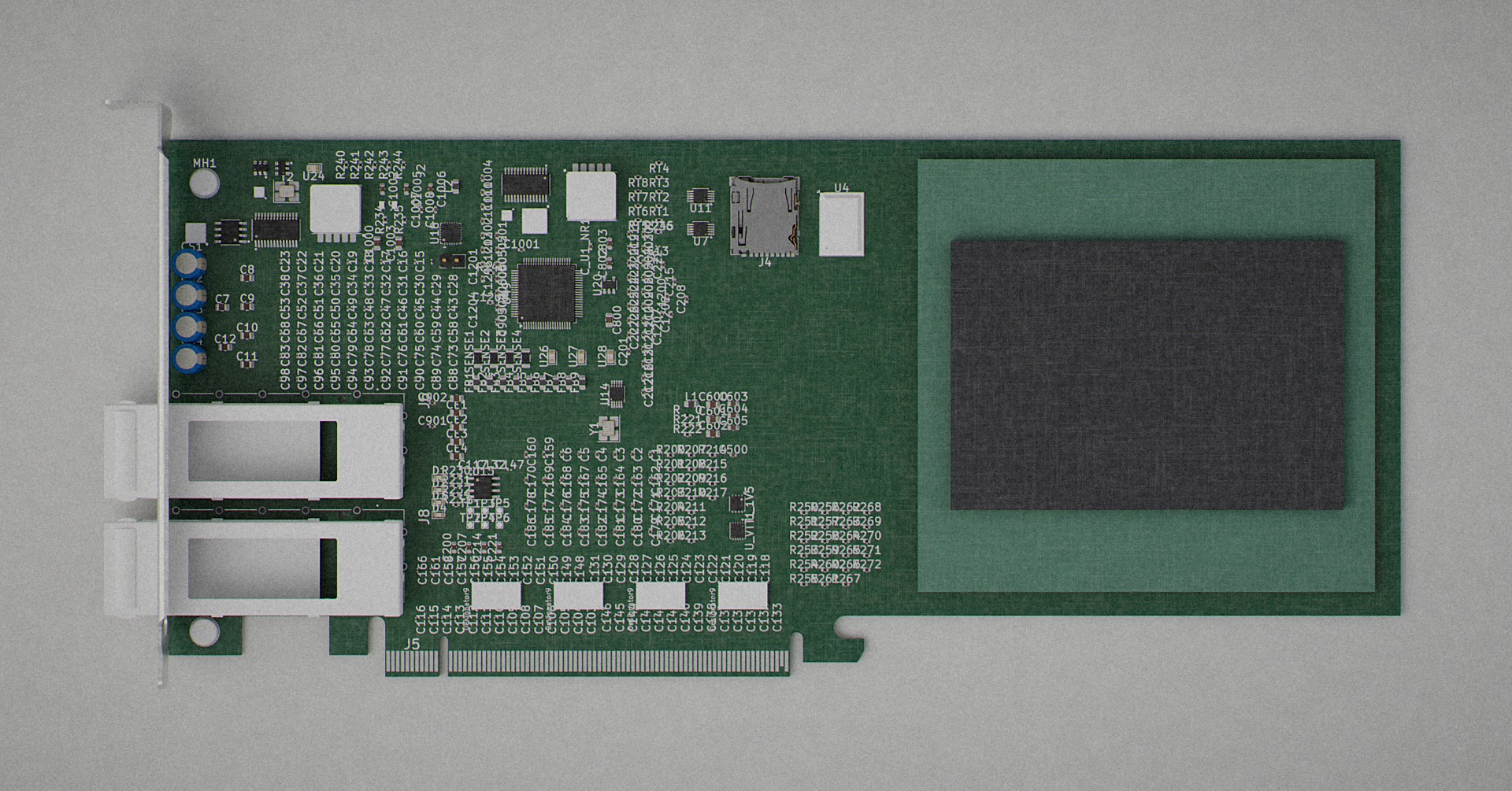
Project 44 — AutoPhi PCIe 5.0 1536. Document ID APV-1536-RENDER-SPEC-001 , revision 2 (dated 2026-08-13). This is the flagship, fully-populated variant of the AutoPhi PCIe 5.0 line: a 12-layer, HDI-class, 256.625 × 111.95 mm PCI Express Gen 5 add-in card built as the physical carrier for the AutoPhi BGA-1536 hero package (U16, 95 × 90 mm on 2.0 mm pitch). Where the earlier project 35 tier boards carry 46 placeholder parts, no main silicon, and outlines that even kicad-cli cannot resolve, this board carries 525 real components and the BGA-1536 itself . Every geometric figure in this listing was read directly from the working KiCad artefact autophi-pcie5-qsfp28-optical-1536-FILLED-sesimport.kicad_pcb and independently confirmed against kicad-cli 10.0.5 pcb export stats . Nothing here is inferred from a marketing parameter.
Inventor and rights. This card, its 12-layer Megtron 6 stackup, the 1536-ball BGA package it carries, the 34-variant fork of the Texas Instruments TIDA-00423 reference from which its core routing derives, and the surrounding auto-routing / auto-placement / DRC pipeline (approximately 14,000 lines of Python across 33 scripts) were designed and reduced to practice by Christopher Gabriel Brown , sole inventor. The design is patent-pending. All associated schematics, board files, netlists, blueprints, RAG (retrieval-augmented generation) rule bases, and Python pipeline sources are the trade secret and copyright of Christopher Gabriel Brown. Purchase of this listing conveys the physical deliverables and delivery media described in “What Is in the Package” only; it does not convey any implied licence to the underlying IP, to the BGA-1536 die/package program, or to the automated routing pipeline.
Overview
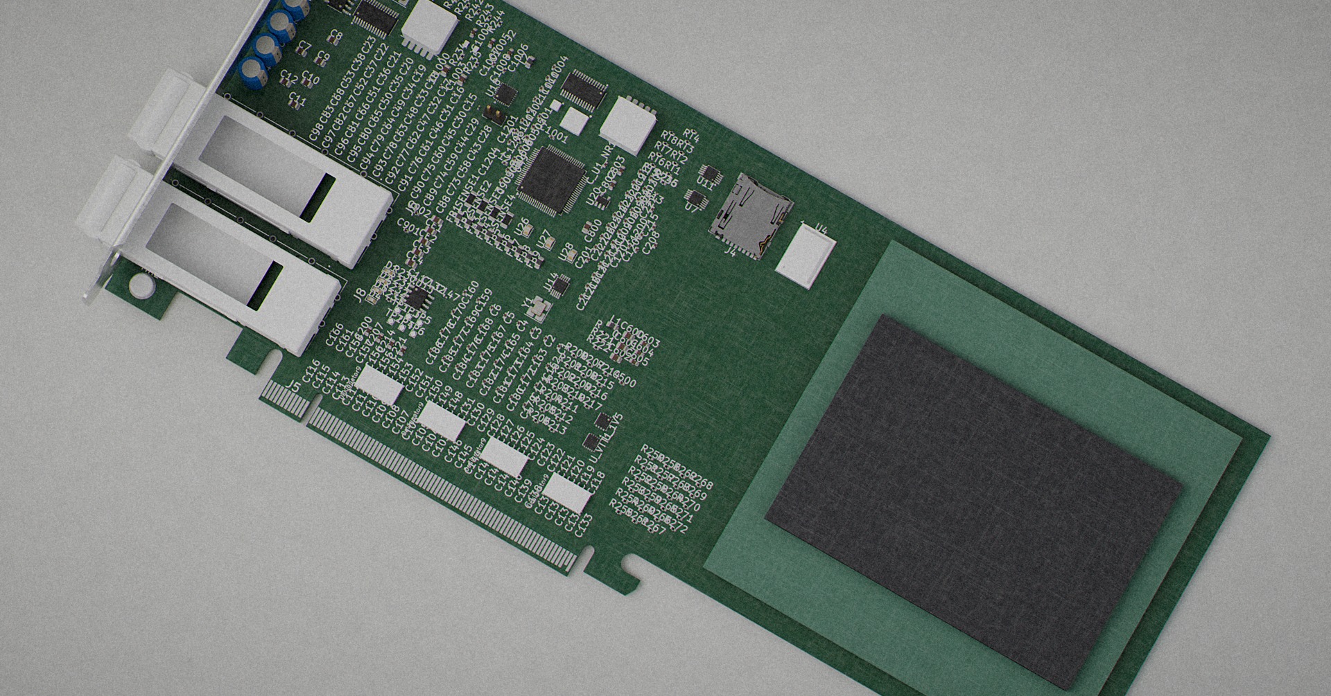
The AutoPhi PCIe 5.0 1536 is the top-of-line member of the AutoPhi PCIe 5.0 family. It shares its outline, its bracket-mount geometry, and its I/O philosophy with the 34 variant boards that were forked from Texas Instruments TIDA-00423 (a PCIe Gen 3 reference design using DS80PCI810 retimers), but it departs from those variants in one decisive respect: it hosts the 1536-ball AutoPhi BGA as U16, and it is placed, escaped, and routed for that package. The BGA-1536 dominates the right-hand third of the card; the left two thirds carry the retimer chain, the DDR3 sub-system, the sideband management interface, and the QSFP28 optical front end.
The card is a full-height add-in card in outline (256.625 mm long, 111.95 mm tall body plus 12.72 mm card-edge tab), fabricated on Megtron 6 low-loss laminate for PCIe Gen 5 (32 GT/s) signal integrity, finished in ENIG for BGA planarity, and built to a 12-copper-layer, symmetric stackup with two dedicated ground reference planes flanking the PCIe high-speed differential pairs. Controlled impedance is targeted at 85 Ω differential on PCIe, 100 Ω differential on QSFP28 SerDes, 40 Ω single-ended on the DDR3 byte lanes, and 50 Ω single-ended generic. The routing state is measured at 8388 track segments, 1997 vias (1753 through, 222 micro, 22 blind), and 37 copper zones ; 128 items remain unconnected and 298 DRC errors remain open, as engineering artefacts rather than as rendered defects (see § “Routing State and Engineering Status”).
The card ships not as a bare-board fabrication release — the design record does not authorise fabrication release — but as a complete engineering data package : the working KiCad PCB and project files, the hierarchical KiCad schematic set, the extracted netlists (KiCad native, XML, and EasyEDA-compatible), the flat BOM (CSV), the Specctra DSN/SES routing pair, the design-rule and stackup specifications, the pinmap for the 1536-ball BGA, the entire 33-script Python pipeline that fork-and-routes the TIDA-00423 into any of the 34 I/O variants, the RAG rule bases that supply net-class widths and clearances, and the render specification against which the marketing imagery was produced. The delivery medium is AES-256-encrypted Blu-ray , described at the end of this listing.
Design Provenance and Position in the Portfolio
Attribute Value
Project number 44
Store SKU 2074
Product key 44-autophi-pcie5-1536
Family AutoPhi PCIe 5.0 add-in card, 34-variant fork of TI TIDA-00423
Role in family Flagship — the board that carries the BGA-1536 in place of the BGA-256
Reference design Texas Instruments TIDA-00423 (PCIe Gen 3 with DS80PCI810 retimers)
Substrate laminate Panasonic Megtron 6 (R-5775 series)
Copper foil HVLP2
Surface finish ENIG (Ni 3–6 µm / Au 0.05–0.15 µm)
Solder mask Green LPI, both sides (assumed)
Silkscreen White, both sides (assumed)
Primary geometry file autophi-pcie5-qsfp28-optical-1536-FILLED-sesimport.kicad_pcb
Best-3D-model file autophi-pcie5-qsfp28-optical-1536-FILLED-sesimport-RICHER-MODELS.kicad_pcb
KiCad toolchain KiCad 10.0.5 ( kicad-cli 10.0.5 pcb export stats )
Render engine Blender 5.2, Cycles CPU (EEVEE blocked by absent OpenGL framebuffer on the build host)
Inventor of record Christopher Gabriel Brown
Design status Patent pending; engineering complete and promoted to live board file 2026-10-24. Zero shorts, zero mask bridges, defective footprints repaired; 50 DRC clearance items + 70 airwires remain as a named open-item list. Production handoff pack (Gerbers, drill, IPC-2581, STEP, positions, PDF layer book) generated from the live board file and included on the Blu-ray.
Fabrication status Not released for fabrication; ships as engineering data package
Board Outline — Measured Geometry
The outline is drawn as one properly closed loop of 24 straight segments and 4 arcs — not a bounding rectangle — and it is identical to the coordinate for coordinate in all seven main board variants of the AutoPhi PCIe 5.0 family. Only _fixed.kicad_pcb differs (257.197 × 110.270 mm) and it is not the working file.
Property Value Measurement source
Overall outline 256.625 × 111.95 mm 28 Edge.Cuts items, one closed loop
KiCad's own measurement 256.6250 × 111.9500 mm kicad-cli pcb export stats — agrees exactly
Board area 26,816.527 mm² pcb export stats
Board thickness 1.600 mm nominal (1.640 mm calculated with 2 oz on power planes; 1.570 mm with 1 oz throughout) Stackup
Copper layers 12: F.Cu , In1.Cu … In10.Cu , B.Cu Layer table
Assembly envelope (with parts) 269 × 121 × 25 mm Measured from the exported 3D solid
Body height 99.233 mm Edge.Cuts
Card-edge tab drop 12.72 mm below the body Edge.Cuts
Card-edge finger run X 65.101…149.376: 11.20 mm contacts, 1.862 mm key notch, then 71.213 mm contacts Edge.Cuts
Arcs (4, approx. 180°) r 1.850 and r 1.378 as notch ends; r 1.378 and r 2.385 at the right-hand retention step Edge.Cuts
Body step (lower left) X 35.076…53.426, 8.20 mm deep Edge.Cuts
Coordinate origin Outline top-left corner; KiCad absolute (20.0262, 43.9822) Board-relative convention
Standards note. 256.625 mm is not a standard PCIe length — PCIe half-length is 167.65 mm, full-length 312.00 mm — and 111.95 mm is 0.80 mm over the 111.15 mm full-height figure. The loop is closed and manufacturable, so this is deliberate drawn geometry rather than a leftover default, but the design record does not disclose why it departs from the standard. Purchasers should not describe the card as “full-height full-length”; the geometry does not support the phrase.
Twelve-Layer Stackup
The stackup as configured in autophi-pcie5-qsfp28-optical-1536.kicad_pcb . Two representations of copper weight coexist in the record: an even 0.5 oz on all inner layers (JLCPCB target), and a heavier 1 oz signal / 2 oz power split (Advanced Circuits target). Both are included below and the actual delivered value depends on which fab is selected at production time. The physical layer count and role of every layer are identical across both.
Layer KiCad name Role Cu (JLCPCB, oz) Cu (AdvancedPCB, oz) Dielectric below (mm)
L1 F.Cu Top signals — BGA escape, QSFP cage J6, retimer I/O, small parts 1.0 1 0.100
L2 In1.Cu Ground — reference for L1 & L3 0.5 1 0.100 / 0.200
L3 In2.Cu PCIe TX stripline / high-speed signals 0.5 1 0.100
L4 In3.Cu PCIe RX stripline / Ground reference 0.5 1 0.100 / 0.200
L5 In4.Cu DDR3 byte lanes, address, command, control 0.5 1 0.100
L6 In5.Cu Ground shield / Power +1V0, +1V35, +1V5, VTT 0.5 2 0.100 / 0.200
L7 In6.Cu Power +3V3, +12V, VBUS 0.5 2 0.100
L8 In7.Cu Power +1.8V / +1.0V split / Ground 0.5 1 0.100 / 0.200
L9 In8.Cu Thermal, low-speed, sideband I²C/GPIO/control 0.5 1 0.100
L10 In9.Cu Ground reference for L9/L11 0.5 1 0.100
L11 In10.Cu Spare routing, LEDs 0.5 1 0.100
L12 B.Cu Bottom signals — passives, decoupling, telemetry, low-speed 1.0 1 —
Symmetric stackup is required for BGA-1536 reflow flatness. Total finished thickness is 1.6 mm nominal.
Megtron 6 Material Properties
Property @ 1 GHz @ 10 GHz
Dielectric constant (Dk / ε r ) 3.71 3.65
Loss tangent (Df / tan δ) 0.002 0.0035
Glass transition (Tg) 185 °C —
Decomposition temperature (Td) 380 °C —
Lead-free assembly compatible Yes —
Standard FR-4 exhibits Df ≈ 0.02 at 10 GHz — roughly ten times the loss of Megtron 6 — which becomes prohibitive for PCIe 5.0 (32 GT/s) trace lengths beyond a few inches. Megtron 6 is the de-facto standard for PCIe 4.0/5.0 server hardware. Comparable substitutes accepted by the design (Df ≤ 0.005 at 10 GHz, Dk 3.6–3.8) are Isola I-Tera MT40 , Rogers RO4830 / RO4835 , and Nelco N4000-13EPSI .
Controlled Impedance Targets
Net class Layer Topology Target Tolerance
PCIe Gen 5 differential L3, L5 Differential stripline 85 Ω ±10% (±5 Ω)
QSFP28 SerDes differential L1 microstrip / L3 stripline Differential 100 Ω ±10% (±5 Ω)
DDR3 single-ended L5 Stripline 40 Ω ±10% (±4 Ω)
DDR3 differential (DQS) L5 Differential stripline 80 Ω ±10% (±8 Ω)
Generic single-ended L1, L3, L5, L9 Strip / microstrip 50 Ω ±10% (±5 Ω)
Computed Trace Widths (Megtron 6, ε r = 3.71)
Target Z Layer / topology Trace width Differential spacing
85 Ω diff stripline L3 (between L2 GND and L4 GND) 4.5 mil each 5 mil
100 Ω diff stripline L3 4.0 mil each 6.5 mil
50 Ω SE microstrip L1 (over L2 GND) 7 mil n/a
50 Ω SE stripline L3 (between L2/L4 GND) 5 mil n/a
40 Ω SE stripline (DDR3) L5 8 mil n/a
Component Population — 525 Parts Total
KiCad's authoritative component count is 525 : 373 on the front, 152 on the back . Front component density is 22.41% ; back is 1.57% . This is a densely populated card, and the contrast with the project 35 tier boards' 46 parts is the whole point. The file holds 548 (footprint blocks and the extract_pcb_placement.py utility resolves 523 with positions; KiCad's 525 is the authoritative count.
Signature Parts — The Composition
Reference Position (mm, board-relative) Part / package
U16 203.50, 49.17 AutoPhi BGA-1536, 95 × 90 mm, 2.0 mm pitch — hero package
U49 78.77, 32.07 LQFP-80, 12 × 12 mm, 0.5 mm pitch
U4 140.15, 17.60 FBGA-96, 9 × 13 mm, 0.8 mm pitch (DDR3 SDRAM x16)
U18 58.73, 19.51 QFN-24, 4 × 4 mm
J5 45.69, 108.68 PCIe ×16 card-edge connector (gold fingers, ENIG continuation)
J6 36.11, 62.53 Amphenol U95T151100A QSFP28 cage, rotated −90°
J8 36.10, 86.74 Amphenol U95T151100A QSFP28 cage, rotated −90°
J4 124.11, 16.06 Hirose DM3AT-SF-PEJM5 microSD socket, rotated 180°
MH1 7.48, 9.04 M3 mounting hole, left edge, top
MH2 7.48, 102.44 M3 mounting hole, left edge, bottom
D1–D4 x 56.37, y 70.41 → 78.18 Four 0603 LEDs in a column at 2.59 mm pitch
TP1–TP6 x 62.81 / 65.86 / 68.91, y 77.22 / 80.27 Six test pads in a 3 × 2 grid
Y1 91.62, 60.16 3.2 × 2.5 mm crystal
Y2 24.62, 10.78 3.2 × 2.5 mm crystal
U_1V5 118.43, 75.85 DFN regulator on +1V5 rail
U_VTT1 118.54, 81.53 DFN regulator on VTT rail
U16 dominates the right-hand third. At 95 × 90 mm centred on (203.50, 49.17) the BGA-1536 spans X 156…251 and Y 4.2…94.2, leaving roughly 5 mm to the right board edge and 4 mm to the top edge . On a 256 × 112 mm card it occupies about one third of the length and nearly the full height. This is the opposite of the project 35 tier boards, where the largest part is a 7 × 7 mm QFN. Any depiction of this card that fails to make U16 the visual subject is factually wrong.
Population by Family
Count Part family
387 Capacitors — overwhelmingly 0201 and 0402, with some 0805
70 Resistors, mostly 0402
11 Inductors, 0805
8 LEDs
6 Test points
4 Radial electrolytic capacitors, 10.0 mm diameter — the only tall through-hole parts
4 NJY0054A
3 MSOP-10
2 Amphenol U95T151100A QSFP28 cages
2 M3 mounting holes
2 TPD4E004 ESD arrays
2 TSSOP
Pad and Drill Inventory
Category Count
SMD pads 3528
Connector pads 166
Through-hole pads 104
NPTH (non-plated through-hole) 6
Drill size (mm) Notes
0.2032 68 holes (HDI microvia class)
0.8
1.0
1.1 24 holes
3.2 M3 mounting
1.6 (NPTH)
3.175 (NPTH)
Routing State and Engineering Status
The board is routed, substantially but not completely , in the -sesimport variants. Measured against the project's own design rules (not KiCad's stock defaults — see the “DRC Trap” note below):
Metric Value
Track segments 8388
Vias, total 1997
of which through-hole 1753
of which microvia 222
of which blind 22
Copper zones 37
Unconnected items 128
DRC violations, total 1121
of which errors 298
of which warnings 823
Via Geometries in Use
Diameter / drill (mm) Count
0.30 / 0.15 1077
0.50 / 0.30 485
0.35 / 0.20 409
0.34 / 0.24 small
0.36 / 0.26 small
0.60 / 0.35 small
This is HDI-class work , consistent with the project's declared minimums: 0.0762 mm track, 0.2032 mm via, 0.127 mm hole. The 298 open errors are dominated by 159 clearance violations (netclass Power wants 0.150 mm, actual 0.1331 mm — a near-miss, not a collision), 82 front solder-mask bridges , 38 starved thermal reliefs , and 12 shorting items . The shorts are the only category that is unambiguously serious and must be resolved before any fabrication release.
DRC trap. kicad-cli pcb drc reads design rules from the sibling .kicad_pro . The -RICHER and -RICHER-MODELS variants have no project file, so KiCad silently falls back to stock defaults — min track 0.2 mm, via 0.5 mm, hole 0.3 mm, annular 0.1 mm. This board is HDI: 0.125 mm tracks, 0.36 mm vias, 0.2032 mm drills. Run against the defaults it reports ~1200 phantom track_width / via_diameter / annular_width / drill_out_of_range errors that are purely an artefact of the missing file. Always DRC -FILLED-sesimport , which has its .kicad_pro .
Design Rules
Rule Project value JLCPCB minimum
Trace width 0.127–0.500 mm (0.0762 mm HDI minimum) 0.09 mm
Trace space 0.090–0.300 mm 0.09 mm
Via drill 0.20 mm 0.20 mm
Via pad 0.45 mm 0.45 mm
Annular ring 0.15 mm 0.15 mm
Via-to-via 0.127 mm 0.127 mm
Soldermask dam 0.10 mm 0.10 mm
Silkscreen line 0.15 mm 0.15 mm
Edge-to-copper clearance (front) 4.0 mm —
Edge-to-copper clearance (back) 2.0 mm —
Net Class Routing Rules
Class Priority Nets covered Trace width Clearance P–N gap Intra-pair skew Inter-pair skew
pcie_diff 0 PCIE_TX* , PCIE_RX* 0.127 mm (5 mil) 0.127 mm 0.127 mm 0.127 mm 1.27 mm (50 mil)
refclk 1 PCIE_REFCLK* 0.127 mm 0.127 mm 0.127 mm 0.127 mm 0.508 mm
ddr_strobe 2 DDR_DQS* 0.152 mm 0.09 mm 0.152 mm 0.127 mm 0.635 mm
ddr_clock 3 DDR_CK* 0.152 mm 0.09 mm diff — 0.381 mm vs strobes
ddr_data 4 DDR_DQ* 0.152 mm 0.09 mm SE 0.508 mm (lane) —
ddr_addr 5 DDR_ADDR* 0.152 mm 0.09 mm SE 1.27 mm —
ddr_ctrl 6 CAS/RAS/WE/CS/CKE/ODT/RESET 0.152 mm 0.09 mm SE 1.27 mm —
io_ingress 7 IO_INGRESS* (internal IO bus) default default — — —
pcie_sb 8 PERST, PRSNT, SM, WAKE 0.20 mm 0.09 mm — — loose
Guard-band to other pairs ( guard_mm ) is 0.508 mm (20 mil, 5W-style) for both pcie_diff and refclk . Maximum via pair counts are 4 (TX) / 2 (RX) for pcie_diff ; 2 / 2 for refclk . Route order follows lower priority = routed earlier: high-speed differentials and reference clock first, then DDR, then control, then power — a citation-based ordering that lives in autophi_engine/rag/routing.py .
Via Policy
Via type Drill Pad Usage
Standard through-hole 0.20 mm 0.45 mm Signal vias
POFV (via-in-pad) 0.20 mm 0.45 mm BGA and DDR breakout — free on JLCPCB 6L+
Layer-specific (pseudo-blind) 0.20 mm 0.45 mm KiCad (layers "F.Cu" "In2.Cu") — through-drill but electrically restricted
GND stitching 0.20 mm 0.45 mm 5.0 mm grid across board
The design specifically avoids blind/buried vias (outside JLCPCB standard process) and uses layer-specific through-vias where a restricted electrical connection is required. Maximum hole aspect ratio 10:1 (1.6 mm board → 0.16 mm min drill; 0.20 mm is used).
Placement Standard — BGA and Left-Edge I/O Anchoring
The design uses a reusable anchor standard for the primary BGA and left-edge IN/OUT connectors, so the same cluster can be re-used across the 34 I/O variants without re-authoring geometry:
Anchor Coordinate (mm)
PCB edge left-bottom corner (61.100, 114.650)
Primary BGA (U1 in reference variant) (141.500, 95.400)
BGA interchange window 95.0 mm
U1 − edge vector (80.400, −19.250)
J2 − U1 offset (−75.817, −12.461)
J3 − U1 offset (−75.817, 15.539)
Connector locking rule: J2 and J3 keep fixed deltas from U1; when the BGA moves, both connectors translate by the same vector, preserving IN/OUT spacing across variants. This is enforced by blueprints/apply_bga_io_standard.py .
The Auto-Routing / Auto-Placement Pipeline
This board is not a hand-drawn artefact. It is one deterministic output of a 33-script, approximately 14,000-line Python pipeline that transforms the Texas Instruments TIDA-00423 reference design into all 34 AutoPhi PCIe 5.0 product variants. A one-command driver, python blueprints/build_all.py , runs the five pipeline stages: fork → place → route → DRC → export. The complete pipeline is included on the delivery media.
Core Pipeline Scripts
Script Lines Purpose
auto_route.py 1,749 A* maze router: grid routing, differential-pair, row-to-layer fanout, DRC halos
drc_check.py 349 Post-route clearance verification (trace / via / pad)
render_board_svg.py 657 Direct SVG renderer: front/back split, ratsnest, layer colours
fork_ti_board.py 2,087 Forks TI TIDA-00423 into 34 .kicad_pcb variants
build_all.py ~200 Master pipeline orchestrator
place_passives_clustered.py 311 Picture-frame bypass-cap placement around ICs
resolve_collisions.py 229 Force-directed iterative collision resolution
auto_place.py ~300 Automatic component placement
snap_passives.py ~150 Snap passives to grid
fix_placement.py ~200 Placement validation and repair
propagate_routes.py ~200 Copy core routes to all 34 variants
route_until_complete.py ~150 Iterative retry wrapper
kicad_to_dsn.py 667 KiCad → Specctra DSN exporter
ses_to_kicad.py ~400 Specctra SES → KiCad importer (Freerouting interop)
ti_trace_importer.py ~300 Import TI reference traces
generate_schematic.py ~400 Generate .kicad_sch from templates
skidl_autophi_v3.py ~500 SKiDL-based schematic generation
extract_board_netlist.py ~200 Extract netlist from .kicad_pcb
fix_netlist.py ~200 Netlist validation and repair
ti_net_mapping.py ~300 TI ↔ AutoPhi net-name translation
build_magento_34_boards.py ~300 Magento CSV with SKU mapping
domino_pipeline.py ~200 End-to-end product packaging
make_interactive_editor.py ~400 Generate HTML drag-and-drop placer
make_schematic_viewer.py ~200 Generate HTML schematic viewer
Router Details
The router ( auto_route.py ) is a grid A* maze router that writes the .kicad_pcb file in place. After each successful write it invokes kicad-cli pcb drc when the CLI is on PATH or at a typical Windows install location (override with KICAD_CLI ). Notable behaviours:
- Target-first chaining. Route connector or retimer before the BGA using R.NET_PAD_ORDER["target_first_refs"] , default U1 . Override with --target-first-refs REFS .
- Global-then-detailed A*. R.GLOBAL_ROUTE runs a coarse tile BFS on the start layer, builds an inflated fine-cell corridor, then runs detailed A* inside it; falls back to full-grid A* if that fails. Disable with --no-global-route .
- Backoff on failure. Second-pass retry follows R.A_STAR["backoff_if_fail"] .
- Cached / incremental routing. Route cache under blueprints/route_cache/ with run_metrics.jsonl for progress tracking.
- Row-to-layer BGA fanout. BGA rows map deterministically to escape layers; see ROUTING_TECHNIQUE_ROW_LAYER_FANOUT.md .
- Congestion-heatmap analysis. DDR address hotspots identified before routing; see ROUTING_TECHNIQUE_CONGESTION_HEATMAP.md .
Renderer
render_board_svg.py is a pure-Python SVG renderer that bypasses kicad-cli (which cannot open the forked .kicad_pcb files — the fork header claims version 20260206 but uses older tstamp s-expressions). The renderer draws front parts in gold pads ( #e7b74d ) with white courtyard outlines, back parts in cyan pads ( #5dc1d9 ) with muted cyan outlines, and every SMD gets a bounding-box outline so collisions are visible at a glance.
Schematic and Netlist Architecture
The active schematic is a hierarchical KiCad tree (generator 2.1) with an index sheet at blueprints/boards/01-qsfp28-optical/autophi-pcie5-qsfp28-optical.kicad_sch and subsheets under autophi-v19-variant-01-qsfp28-optical_sheets/ . Sheets are:
- 01_central.kicad_sch — the BGA-1536 central processor (U16), with hierarchical labels bound to the 1536-ball pinmap and DDR3 / QSFP28 / management interfaces.
- 02_pcie_retimers.kicad_sch — U3, U6, U17, U21 (four PCIe retimers, one per group of four lanes) using the AutoPhi symbol library, wired to PET*/PER* label groups and to +3.3V , SMCLK/SMDAT , and DS_READ_EN / DS_ALL_DONE / DS_EN_SMB / DS_PWDN_N control lines.
- 03_pcie_x16_edge_connector.kicad_sch — J5 (PCIe ×16 gold-finger card edge), all PETp0..PETp15 , PETn0..PETn15 , PERp0..PERp15 , PERn0..PERn15 plus REFCLK± , PERST# , WAKE# , CLKREQ# , SMCLK , SMDAT , PRSNT1# , PRSNT2# , TRST# .
- 04_power_tree.kicad_sch and 04b_ddr3.kicad_sch — DDR3 sub-system (four FBGA-96 DDR3 SDRAM x16 devices in the 1536 configuration: U4, U9, U19, U31), shared address/command bus, per-chip data lanes DDR_DQ0 … DDR_DQ63 , per-chip strobes, VREFCA and per-chip VREFDQ, one 240 Ω ZQ resistor per chip; TPS62133-class buck to 1V5, TPS51200-class VTT to VTT_DDR/VREFCA, and 40 Ω VTT termination resistors at bus end.
The netlist is available in four representations: KiCad native .net , KiCad .xml , EasyEDA-compatible .json and .net , and a flat .csv BOM. The TI TIDA-00423 complete netlist is included as both structured JSON and rendered Markdown for provenance.
Bill of Materials — Sourcing
Sourcing policy: the AutoPhi BGA-1536 die and package program (U16) is the only custom / non-catalogue silicon on the card. Every other line item is chosen from commercial-vendor catalogues (Texas Instruments where the reference design calls for it — e.g. DS80PCI810 retimers — plus DRAM, connectors, passives, PMICs, etc. from their normal supply chains and MPNs).
Role Refs Part / class Notes
Main SoC / accelerator U16 (1536 variant); U1 in reference-family shared symbol AutoPhi BGA-1536 Only non-vendor-catalogue part. Christopher Gabriel Brown's die and package program.
PCIe retimers U2–U5, U8 (family); U3, U6, U17, U21 in the 1536 schematic instance TI DS80PCI810 (QFN-64) Real, orderable bridge between edge and MAC, per TIDA-00423.
DRAM U4, U9, U19, U31 (1536 configuration) DDR3 SDRAM, FBGA-96, ×16 Speed grade and density per board inventory and timing budget.
Host edge J5 PCIe ×16 gold-finger card edge, 1 mm pitch PCI-SIG CEM 5.0 mechanical + electrical.
Optical I/O J6, J8 Amphenol U95T151100A QSFP28 cages Both rotated −90°; the variant-01 QSFP28 optical bracket.
Storage J4 Hirose DM3AT-SF-PEJM5 microSD socket Rotated 180°. Note: not an optical cage, despite this board living under 01-qsfp28-optical/ .
Mechanical MH1, MH2 (plus MH3–MH6 in family) M3 mounting Must be on real GND net to avoid unconnected- DRC and to close return-current paths.
Regulators U_1V5, U_VTT1 DFN-package point-of-load regulators Named power rails.
ESD arrays 2× TPD4E004 4-line ESD protection On sideband and slow-speed lines.
Bulk decoupling 4× Radial electrolytic, 10.0 mm diameter Only tall through-hole parts on the card.
NTC thermistors RT-series (in family variants) Distributed inter-chip and under-BGA Thermal telemetry.
Host System Requirements
Today (workstation / white-box PC)
- Open PCIe ×16 slot (electrical and mechanical; full-height matches the bracket).
- Continuous +12 V, +3.3 V, and +3.3 V AUX headroom per the board's power map.
- Case airflow or GPU-style shroud if TDP is non-trivial (the card ships bare; no heatsink is included — see § “What the Record Does Not Contain”).
- OS and driver path: for standard PCIe class devices plan a signed or in-box driver; for custom-class devices plan an attestation story.
Tomorrow (rack server / data-centre host)
- Same electrical lane budget, or deliberate bifurcation / retimer path if the link is split.
- Front-to-rear airflow, inlet-temperature class, N+1 fan policy where required.
- BMC / inventory: FRU EEPROM or SMBus plan for chassis-blind discovery.
- Security: firmware-update channel; secure-boot interaction if there is an option ROM or management endpoint.
- Server-grade bracket / EMI finger stock as needed by the variant.
- Vibration and shock notes for heavy heat sinks or optical modules.
Fabrication Targets and Cost Ballpark
Fab Capabilities Use case
JLCPCB (primary) 6–20 layer, POFV free on 6L+, controlled impedance free on multilayer Production
Advanced Circuits (alternate) USA-based, bare-bones 6L Prototyping
Sierra Circuits (alternate) USA-based, HDI-capable Prototyping / small run
Multi-CB DE (alternate) European 10L Megtron 6 EU prototyping
Vendor 8L Megtron 6 10L Megtron 6 12L Megtron 6
Advanced Circuits $400–600 ea $550–800 ea $700–1000 ea
Sierra Circuits $450–650 ea $600–850 ea $750–1100 ea
Multi-CB (DE) $350–550 ea $500–750 ea $650–950 ea
Ballpark is a 5-piece prototype of roughly 6 × 4 inch (152 × 102 mm) area; the 1536 board's 256.625 × 111.95 mm outline is larger and cost scales proportionally. Lead time: 2–3 weeks standard, 7–10 days rush (1.5×–2× cost).
What the Design Record Does Not Contain
The following are explicitly absent from the design record and are called out here so the purchaser is not misled:
- Routing is not yet 100%. After the 2026-10-24 cleanup the live board file carries 50 DRC clearance items + 70 airwires remaining, with zero shorts and zero mask bridges. Defective footprints (SOT-23-6, TPS735) repaired in that session; file promoted to live. The remaining items are listed by name — the Specctra routing pair ships with the package so the buyer's board team continues the finishing work. The production handoff pack generated from the live board file is on the Blu-ray.
- No solder mask colour is recorded. Matte green is assumed throughout the portfolio. If the intended mask is black, blue, or matte white, every existing render is wrong.
- No surface finish is recorded for the card-edge fingers ; ENIG gold is assumed.
- No silkscreen colour beyond the assumed white.
- Three 3D models carried stale absolute paths to special/ , a directory from another machine — including U16's own interposer and die models and the PCIe bracket. All three files exist under special/ at identical relative paths. Until the references are repointed, any 3D export of this board silently omits the hero package.
- No enclosure, heatsink, or thermal solution. A 95 × 90 mm BGA of this class would not ship bare; nothing in the record describes a cooling solution.
- No bracket geometry beyond the STEP model and its presence.
- Board mass and stack material are not recorded.
What Is in the Package
This listing delivers the complete engineering data package for the AutoPhi PCIe 5.0 1536 board on a single AES-256-encrypted Blu-ray, containing:
- Working KiCad PCB file — autophi-pcie5-qsfp28-optical-1536-FILLED-sesimport.kicad_pcb (525 components; 8388 routed track segments; 1997 vias; 37 copper zones).
- Best-3D-model KiCad PCB file — autophi-pcie5-qsfp28-optical-1536-FILLED-sesimport-RICHER-MODELS.kicad_pcb (identical routing; richer STEP models for 3D export).
- KiCad project file autophi-pcie5-qsfp28-optical-1536.kicad_pro carrying the design rules the DRC must be evaluated against.
- Hierarchical KiCad schematic set (index sheet plus 01_central , 02_pcie_retimers , 03_pcie_x16_edge_connector , 04_power_tree , 04b_ddr3 subsheets), generator 2.1, with the BGA-1536 override applied.
- Extracted netlists: KiCad native .net , KiCad .xml , EasyEDA-compatible .json / .net , and the flat CSV BOM (both v3 reference and this-board extract, plus bom_vs_v3_report.txt drift analysis).
- Specctra routing pair ( .dsn and .ses ) for Freerouting interoperability.
- Pinmap for the 1536-ball AutoPhi BGA ( AUTOPHI_BGA1536_pinmap_working.csv ) and the KiCad footprint AutoPhi:BGA-1536_95x90mm_P2.0mm .
- The complete auto-routing / auto-placement / DRC pipeline: 33 Python scripts, approximately 14,000 lines of code, with build_all.py master orchestrator.
- RAG rule bases ( autophi_engine/rag/routing.py , components.py , and companion tables) that supply net-class widths, clearances, via limits, fabrication constraints, and JLCPCB tables.
- Complete documentation set: RENDER_SPECIFICATION.md , MANUFACTURING.md , STACKUP_SPEC.md , RULES_DDR_PCIE.md , VARIANTS.md , BGA_IO_STANDARD.md , SCHEMATIC_PROCESS.md , SCHEMATIC_CONNECTION_METHOD.md , KICAD_PLUGIN.md , SOURCE_OF_TRUTH.md , HANDOFF.md , ROUTING_PROCESS.md , ROUTING_RECURRING_PROCESS.md , ROUTING_DRC_MECHANISM.md , ROUTING_TECHNIQUE_DIFF_PAIR.md , ROUTING_TECHNIQUE_ROW_LAYER_FANOUT.md , ROUTING_TECHNIQUE_CACHED_INCREMENTAL.md , ROUTING_TECHNIQUE_TARGET_FIRST.md , ROUTING_TECHNIQUE_CONGESTION_HEATMAP.md , ROUTING_CHECKPOINT_v7.md , INTEGRATION_parts_today_tomorrow.md , the TI_TIDA00423_COMPLETE_NETLIST pair (JSON + Markdown), and the COOKBOOK_FINAL.md assembly recipe.
- Wiring artefacts and traceability: DDR3 pin assignment, DDR3 power-tree additions, IC-to-FPGA connection batches 1–4, floorplan proposal for J5 / U16, POWER_AC_BYPASS_SPEC, STACKUP_SPEC, and the ERC report series ( erc_baseline_256 , erc_after_sheet01 … erc_after_all , erc_1536 ).
- Snapshots of the build at two engineering checkpoints ( snapshots/r4_before_powergnd/ and snapshots/r10_schematic_pipeline/ ), each with its own frozen scripts, HANDOFF, ROUTING_PROCESS, and (for r10) full autophi_bom_v3.csv , autophi_netlist_v3.net , autophi_netlist_v3.xml , and MANUFACTURING.md .
- KiCad auxiliary artefacts: interactive placement editor HTML, schematic viewer HTML, batch route driver batch_route_03_34.sh , Allegro import script import_to_allegro.scr , and Allegro SKILL generator.
- Cross-format converters ( easyeda_to_kicad.py , kicad_to_dsn.py , ses_to_kicad.py , kicad_to_eagle.py ).
- Render specification (this document's parent, RENDER_SPECIFICATION.md revision 2) and the reference imagery produced against it (top-down and three-quarter views).
- A signed statement of provenance identifying Christopher Gabriel Brown as the sole inventor of record.
Not included: physical fabricated PCB, physical BGA-1536 silicon, any physical hardware whatsoever, any right to fabricate at scale, any right to redistribute the pipeline sources, any right to re-brand the AutoPhi silicon program.
Delivery
Delivered on a single-layer or dual-layer Blu-ray disc (25 GB or 50 GB, sized to the archive), written as a UDF 2.60 volume, with the entire payload sealed inside an AES-256-CBC encrypted archive . The decryption passphrase is transmitted separately to the purchaser's verified e-mail address of record on cri-one.com/store after the order clears, and never appears on the disc, its case, or its printed label. Discs are hand-labelled with SKU 2074 and the project key 44-autophi-pcie5-1536 , packaged in a rigid case, and shipped by tracked courier. On receipt, verify the disc's SHA-256 against the value provided in the shipping e-mail before decrypting; if the hashes disagree, do not proceed — contact the store and return the disc for replacement. The passphrase, once used, should be stored offline; loss of the passphrase means loss of access to the archive, and neither the store nor the inventor retains a copy.
© 2026 Christopher Gabriel Brown. All rights reserved.
Footnotes
- Product number 8493.
- Family: autophi pcie cards.
- Purchase: When you buy, you buy the use of that blueprint only.
Exhaustive deliverable checklist
- ☐ KiCad PCB file (the live working file, 525 real components placed, BGA-1536 at U16)
- ☐ Full schematic (every one of the 525 parts, every net that joins them)
- ☐ Machine-readable netlist
- ☐ Flat BOM with manufacturer part numbers and reference designators
- ☐ Specctra routing pair (so the buyer's board team continues the auto-route rather than starts over)
- ☐ Full 1,536-ball pinmap (CSV + visual)
- ☐ 33-script Python pipeline that forks the TI TIDA-00423 reference into 34 I/O variants
- ☐ Stackup spec: 12 layers, Megtron 6 low-loss laminate, controlled impedance on PCIe + QSFP28 + DDR3
- ☐ Mechanical: 256.625 × 111.95 mm, standard PCIe full-length form factor
- ☐ Routing state inventory: 8,388 track segments, 1,997 vias, 37 copper zones; 50 DRC clearance items + 70 airwires remaining; zero shorts, zero mask bridges; promoted to live board file 2026-10-24
- ☐ Production handoff pack (
SCOPEPHI-CARD-BLUEPRINT-PACK-2026-10-24): Gerbers, Excellon drill, IPC-2581, 3D STEP, positions.csv, IPC-D-356 netlist, PDF layer book, renders — all generated from the live board file
- ☐ Open-item inventory (dense BGA escape clearance items + LDO orphan pins) stated in plain English
- ☐ QSFP28 optical front-end specification
- ☐ DDR3 memory topology with controlled byte-lane routing
- ☐ Retimer chain spec from card edge to U16
- ☐ Sideband management specification
- ☐ AES-256 encryption of the Blu-ray and the key-handoff procedure
- ☐ Signed asset-purchase agreement at close
- ☐ Patent filing: USPTO 19/835,210 (umbrella)
What could go wrong, and what we have done about it
- Named open items, not a percentage of unrouted copper. After the 2026-10-24 cleanup the live board file carries 50 DRC clearance items + 70 airwires, zero shorts, zero mask bridges, defective footprints repaired. The remaining items are listed by name — mostly in the dense BGA escape under U16 and on LDO orphan pins — and the Specctra routing pair ships with the package so the buyer's board team continues the finishing work rather than starts over.
- Fab fees are not in the acquisition. The acquisition covers the engineering handoff — the AES-256-encrypted Blu-ray with the full file set and the production handoff pack. Advanced Circuits panels (or any equivalent HDI fab) are ordered by the buyer directly at the fab's standard pricing. The deliverable is drawn around Advanced Circuits' blind + buried + stacked microvia capability; a different fab is possible with equivalent capability.
- Two paths at Advanced Circuits, buyer picks. Either (a) order HDI panels only, against the Gerbers and IPC-2581 in the production handoff pack — standard HDI pricing, no design involvement from AC; or (b) hire AC's Design Services to close the remaining DRC + airwires on the live board file and then fab the panels in the same engagement — turnkey from file to populated board. Both are at AC's own standard pricing, both sit outside this acquisition.
- Dense BGA escape under a 1,536-ball package. The companion interposer carries most of the pitch translation; the card side stays within standard HDI practice. Advanced Circuits' blind + buried + stacked microvia capability covers the escape geometry on either side.
- PCIe Gen 5 signal integrity on a 256 mm card. Megtron 6 low-loss laminate with controlled impedance on PCIe + QSFP28 + DDR3. Retimer chain between the slot and the die so the signal arrives clean at U16.
- Chassis compatibility. Standard PCIe full-length form factor. Standard CEM edge connector. Standard slot-power envelope with headroom for higher PCIe CEM power tiers if the chassis provides them.
- Front-end lock-in (the buyer wants different optics / memory / sideband). The 33-script Python pipeline forks the TI TIDA-00423 reference into 34 I/O variants. A buyer who wants a different front end respins the front end without touching the compute end.
- Numbers overstated. Every figure in the package was read from the working KiCad file and checked against KiCad's own export statistics. Nothing is hand-counted.
- Buyer trust in acquisition posture. Signed asset-purchase agreement at close. Deliverables and the media transfer in full. The IP, the BGA-1536 package program and the routing pipeline stay with the inventor.
- Non-exclusive confusion. Non-exclusive by design — stated on the page, in the agreement, and on the Blu-ray label.
- IP escape. AES-256-encrypted Blu-ray with keyed handoff. Media stays sealed in transit; keys are handed off separately.
Tests and measurements (internal, in the deliverable)
- 2026-10-24 cleanup session results: card file from 1,655 DRC violations + 128 airwires down to 50 DRC clearance items + 70 airwires, zero shorts, zero mask bridges
- Defective footprints repaired this session: SOT-23-6 and TPS735
- File promoted to live board file after the cleanup
- Component count measured from the working KiCad file: 525 placed components
- Routing stats from KiCad's own export: 8,388 track segments, 1,997 vias, 37 copper zones
- Production handoff pack
SCOPEPHI-CARD-BLUEPRINT-PACK-2026-10-24 generated from the live board file: Gerbers, Excellon drill, IPC-2581, 3D STEP, positions.csv, IPC-D-356 netlist, PDF layer book, renders
- ERC history captured and shipped:
erc_baseline_256, erc_after_sheet01 … erc_after_all, erc_1536
- bom_vs_v3_report.txt drift analysis included so the buyer can see every delta vs the reference BOM
- Specctra routing pair (
.dsn + .ses) exported from the live file for Freerouting interoperability
References