
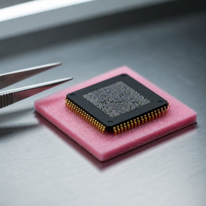
32-quantum-battery-seed-two
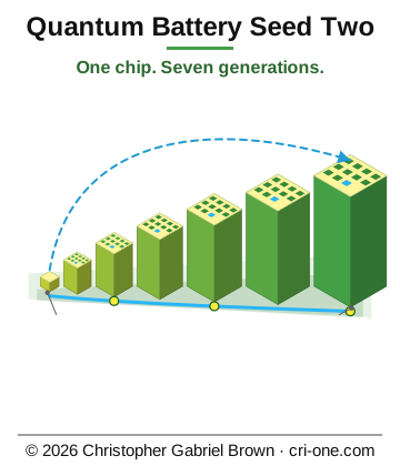
Asset valuation: $7,000,000,000. Master index of all projects: PROJECTSINDEX. Last edited: 2026-05-02 Status: Second-generation quantum-battery seed bundle Maturity (per PACKAGEARCHITECTURE.md): L4 (Tape-out / Mass-Manufacturable) — bundles foundry-ready content
Think of a set of nesting boxes where every box holds ten of the box below it and speaks the same language to the one above. That is Quantum Battery Seed Two. It takes the Project 05 Quantum Battery chip and builds it into complete power systems at seven scales, from a single sub-millimetre die delivering milliwatts up to a million-cell industrial plant delivering tens of terawatts. The controller interface is identical at every tier, so understanding one means understanding all seven.
The building block is the core quantum battery loop: LED nano-charging drives quantum dot arrays, Peltier-based electromagnetic cooling with no moving parts and no fluid reclaims the waste heat, and a quantum execution unit manages the energy-cycle state, all on an AES copper-tin alloy substrate. Seed Two wraps that loop in standardised aggregation: power bus arbitration with efficiency-weighted load balancing, 128-bit telemetry frames passed child to parent, an eleventh hot-spare unit at every tier for N+1 failover, and grid-tie from the array level up with SCADA, DNP3, IEC 61850 and black-start.
The Seed Pack is a 19-inch 42U cabinet written for data centre racks, and a data centre campus is one of the eight deployment profiles, so a datacenter operator can start at the tier that fits the floor. The deliverable is a 17,543-file archive: complete Verilog RTL in ten modules, 350 pre-configured variants, Python generators, four architecture specifications, seven per-generation blueprints, foundry handoff packages and 64-layer GDSII. The engineering buyer walks away with foundry-ready content; the underlying inventions stay with the inventor.
Description
Quantum Battery Seed Two — Scalable Energy System IP
Quantum Battery Seed Two is a seven-generation scaling series that takes the Project 05 Quantum Battery chip and builds it into complete power systems at every scale — from a single sub-millimetre die delivering milliwatts, up to a million-cell industrial power plant delivering tens of terawatts. Each generation aggregates 10 units of the generation below it through a standardised recursive controller interface. One chip. Seven generations. Million-cell industrial power.
Momentum output is paramount. The same photon momentum transfer engine (p = h/λ = E/c) on AES semiconductor substrate drives ultra-fast charge/release cycling at every tier. The core quantum battery loop — LED nano-charging drives quantum dot arrays, electromagnetic cooling reclaims waste heat, the quantum execution unit manages energy-cycle quantum state — is the atomic building block. Seed Two wraps it in standardised aggregation layers with power bus arbitration, distributed control, health monitoring, and N+1 redundancy at every level.
The deliverable is a 17,543-file archive encompassing complete Verilog RTL, 350+ JSON variant configurations, Python generation and scaling tools, four architecture specifications, seven per-generation blueprints, foundry handoff packages, GDSII layout data (64-layer), EDA flow output, synthesis reports, and full documentation. File breakdown by type: 5,436 JSON manifests; 3,536 EDA reports (.rpt); 1,527 text files; 1,305 SVG figures; 1,024 logs; 913 Markdown documents; 610 TCL scripts; 506 Verilog HDL files; 272 DEF (design exchange format) files; 252 SDC timing constraints; 242 HTML files; 216 SDF timing annotation files; 156 Python scripts; 144 Liberty library files; plus archives, GDSII layout, and supporting material.
The Seven Generations (G0 – G6)
Gen Name Scale / Form Factor Active Cells Power Range Efficiency Storage Burst Bus Voltage Use Cases
G0 Seed Cell Chip ( 1 10 mW – 2.5 MW 84 – 98 % 1,500 Wh (20 layers) 75 MW 3.0 – 4.2 V DC (on-die) IoT sensors, medical implants, wearable devices, portable electronics, small motors
G1 Seed Module Board (100 mm × 150 mm PCB) 10 (+1 spare) 25 MW – 500 MW 82 – 96 % 15,000 Wh 750 MW Cell-native parallel (on-board copper) Drones, electric vehicles, portable generators, field equipment, marine vessels
G2 Seed Pack Cabinet (19″ 42U rack, 600 mm × 1070 mm × 2000 mm) 100 (+10 spare) 500 MW – 5 GW 81 – 95 % 150 kWh 7.5 GW 48 V DC (backplane busbar with per-module circuit breakers) Office buildings, data centre racks, ships, large vehicles, commercial HVAC
G3 Seed Rack Container (20′ ISO, 6.1 m × 2.4 m × 2.6 m) 1,000 (+100 spare) 5 GW – 50 GW 80 – 94 % 1.5 MWh 75 GW 400 V DC (heavy-gauge busbar, ring topology with disconnect switches) Campus microgrid, military forward base, small utility grid, mining operation
G4 Seed Array Facility (~50 m × 50 m outdoor) 10,000 (+1,000 spare) 50 GW – 500 GW 80 – 93 % 15 MWh 750 GW 11 kV AC (medium-voltage cable, ring with switchgear) City district, industrial park, large campus, airport
G5 Seed Farm Site (~500 m × 500 m generation site) 100,000 (+10,000 spare) 500 GW – 5 TW 80 – 92 % 150 MWh 7.5 TW 110 kV AC (high-voltage line, radial with substation) Metro grid, regional power, major city, export power
G6 Seed Plant Industrial (~5 km × 5 km complex) 1,000,000 (+100,000 spare) 5 TW – 50 TW 80 – 91 % 1.5 GWh 75 TW 500 kV AC (extra-high-voltage, mesh with switchyard) National base load, continent-scale generation, export to neighbours
Every generation uses the same recursive controller architecture: each tier manages 10 sub-units through a standardised interface. A Seed Plant is 10 Farms; each Farm is 10 Arrays; each Array is 10 Racks; each Rack is 10 Packs; each Pack is 10 Modules; each Module is 10 Cells. The interface contract is identical at every level, so understanding one tier means understanding all seven.
What Seed Two Inherits from Project 05 (the G0 Cell)
- LED Power Recycling (Tech #1) — 90 % efficiency, 32 harvester zones. Converts waste-heat photons to electrical energy via photovoltaic conversion on AES substrate.
- Vertical Threading (Tech #2) — 12,000 TSVs/mm² for high-density layer stacking.
- Chiplet Stacking (Tech #3) — up to 500 layers of vertically integrated chiplets.
- EM Cooling (Tech #6) — 97 % efficiency, 32 independent thermal zones. Peltier-based electromagnetic heat extraction with no moving parts, no fluid. Extracted heat feeds back to the LED power recycler (90 % recapture).
- Quantum Battery Layers (Tech #7) — 20 layers, 1,500 Wh capacity, 75 MW burst power.
- Quantum Execution Unit (Tech #8) — 16-instruction quantum gate set for energy-cycle operations.
- Momentum Output Engine — photon momentum transfer (p = h/λ) driving ultra-fast charge/release cycling from 1× to 200,000,000× fold.
- Auto-Managed Power Export Controller — surplus power output with dynamic self-consumption tracking, partial burst export, auto-throttle (below 25 % charge), auto-boost (above 90 % charge), rate smoothing over 4 cycles, and 48-bit lifetime accumulators for infrastructure-scale energy tracking.
- AES Semiconductor Substrate (Project 14, USPTO 19/449,352) — Cu-Sn alloy. 400 W/m·K thermal conductivity (2.7× silicon). 12,000 cm²/V·s electron mobility. 0.8 eV direct bandgap. $5/kg material cost. Semiconductor score 100/100.
What Seed Two Adds
- Standardised tier controller architecture (recursive 10× aggregation, same state machine at every level).
- Power bus arbitration with efficiency-weighted load balancing, ramp-rate limiting (10 % max change per cycle), and fault isolation.
- Distributed health monitoring and telemetry aggregation (128-bit telemetry frames, child-to-parent propagation).
- N+1 redundancy with automatic failover at every tier (11th unit hot spare).
- Thermal management scaling (EM cooling coordination across tiers, from on-die at G0 to industrial cooling plants at G6).
- Grid-tie capability at G4+ (SCADA, DNP3, IEC 61850, ICCP/TASE.2, OpenADR, ISO/RTO market interface, frequency regulation, anti-islanding, black-start).
- 8 industrial deployment profiles (smart building, EV fleet charging hub, data centre campus, city district grid, regional power grid, national base load, military forward base, offshore platform).
- 350 pre-configured system variants across all 7 tiers (50 per generation).
- 2 Python generators for custom configuration and scaling calculations.
The 10 Verilog RTL Modules
Every module shares a common set of parameterised widths: POWER_WIDTH = 64 , HEALTH_WIDTH = 32 , TELEM_WIDTH = 128 , CONFIG_WIDTH = 32 , CONFIG_ADDR_W = 8 , TEMP_WIDTH = 16 , EFF_WIDTH = 16 . Tier controllers additionally carry NUM_UNITS = 10 and NUM_TOTAL = 11 (10 active + 1 spare). All signals are active-high except the global active-low reset rst_n .
# Module Name File Generation Role Key Additions Over Base Pattern
1 seed_cell_wrapper seed_cell_wrapper.v G0 Wraps Project 05 quantum_battery_system in the standardised tier interface. Translates 16-bit QBS native ports to 64-bit tier power bus. Configuration registers at addresses 0x00 (momentum fold target), 0x01 (max power limit), 0x02 (thermal limit, 0.1 K units, default 398.15 K / 125°C). Enable gating holds the cell in reset when the parent de-asserts enable . Over-temperature fault detection. 128-bit telemetry frame packing: power export [127:112], battery level [111:96], temperature [95:80], efficiency [79:64], momentum fold [63:48], reserved [47:0]. Behavioural simulation model of quantum_battery_system included for testbench verification (4-cycle startup sequence, auto-throttle below 25 %, auto-boost above 90 %, rate smoothing).
2 seed_module_ctrl seed_module_ctrl.v G1 Manages 10 Seed Cells + 1 hot spare on a PCB module. Implements the 8-state controller state machine (see below). Efficiency-weighted proportional load balancing across cells. Sub-unit interface: 11 × 64-bit power request/output/available buses, 11 × 16-bit efficiency/temperature, 11 × 32-bit health status, 11 × 128-bit telemetry. Configuration broadcast to all active units. Telemetry aggregation: sum power, max temperature, weighted average efficiency. Health status word: fault [31], spare_available [30], unit_active [29:20], unit_faulted [19:10], reserved [9:0]. Fault reported to parent only when no spare remains. Template for all higher-tier controllers (same interface shape, same state machine).
3 seed_pack_ctrl seed_pack_ctrl.v G2 Manages 10 Seed Modules + 1 hot spare in a 42U rack cabinet. Same recursive tier interface as G1. 48 V DC backplane bus. Safety interface: per-module solid-state circuit breakers ( circuit_breaker[10:0] ), emergency stop input, smoke/gas detection input, ambient temperature monitoring. Over-temperature warning at 75.0°C (348.1 K), automatic shutdown at 85.0°C (358.1 K). All breakers open on any safety event. Audible/visual alarm output.
4 seed_rack_ctrl seed_rack_ctrl.v G3 Manages 10 Seed Packs + 1 hot spare in a 20′ ISO shipping container. 400 V DC heavy-gauge busbar. Motorised disconnect switches ( disconnect_switch[10:0] ). Liquid cooling loop control: coolant inlet/outlet temperature monitoring, variable-speed pump (0–255, proportional to coolant delta-T), heat exchanger fan speed tracking pump. Fire suppression and gas detection inputs trigger immediate safety shutdown. Network telemetry output (128-bit frame mirroring local telemetry, for Ethernet uplink to central monitoring).
5 seed_array_ctrl seed_array_ctrl.v G4 Manages 10 Seed Racks + 1 hot spare at facility level. 11 kV AC medium-voltage distribution. Grid-tie interface: grid_power_export (64-bit), grid_frequency (0.01 Hz resolution, default 50.00 Hz), grid_voltage (default 11.0 kV), grid_sync_ready , anti_island_trip . SCADA dispatch integration: uses grid_dispatch_target when grid-connected, otherwise falls back to parent power_request . Anti-islanding detection (IEEE 1547): trips if grid disconnects while exporting.
6 seed_farm_ctrl seed_farm_ctrl.v G5 Manages 10 Seed Arrays + 1 hot spare at a power generation site. 110 kV AC high-voltage substation interface. ISO/RTO market interface: market_dispatch (64-bit dispatch signal), market_generation (actual generation reported), market_available flag. Frequency regulation: 4 % droop response, increases output if grid frequency falls below 49.90 Hz, decreases if above 50.10 Hz, adjusting by ±3.125 % (1/32) of the request. Substation connection status monitoring.
7 seed_plant_ctrl seed_plant_ctrl.v G6 Apex of the hierarchy. Manages 10 Seed Farms + 1 hot spare. 1,000,000 active cells. 500 kV AC switchyard interface. National grid operator interface: national_dispatch (64-bit), national_generation , national_available , black_start_capable (can energise a dead grid segment). Plant statistics outputs: total_cells_active (64-bit, counting active farms × 100,000), total_cells_spare (64-bit), lifetime_energy_wh (64-bit accumulator, matching the 48-bit+ cell-level accumulators from Project 05). Lifetime energy accumulates total_power[47:0] every cycle while in EXPORT or later states.
8 seed_power_bus seed_power_bus.v All tiers Shared power bus arbitration module, instantiated at every tier. Request-grant protocol with efficiency × thermal-headroom weighting. Per-unit weight = unit_efficiency × unit_thermal_headroom (both 16-bit, yielding 32-bit weight). Proportional grant: grant[i] = total_request × weight[i] / total_weight , clamped to unit_power_available . Ramp-rate limiting: maximum RAMP_LIMIT (default 10) percent change per cycle, with a minimum ramp of 1 to prevent stall. Bus status outputs: total_granted , total_available , bus_overload (request exceeds available), bus_stable (all grants have converged). Fault mask: faulted units receive zero grant regardless of weight.
9 seed_health_monitor seed_health_monitor.v All tiers Cross-tier health monitoring. One instance per tier controller. Aggregates telemetry from sub-units, generates alerts, tracks performance. Aggregated outputs: total power, max/min/average temperature, average/min efficiency, active/fault/ready unit counts (4-bit each). Alert thresholds: THERMAL_WARN = 348.1 K (75.0°C), EFF_WARN = 80.00% . Four alert flags: alert_thermal , alert_efficiency , alert_fault , alert_degraded (fewer than 10 active units). Packed 32-bit alert_details word. Performance tracking: peak_power (64-bit, highest power seen), uptime_cycles (64-bit counter since last reset).
10 seed_two_tb seed_two_tb.v G0 + G1 Top-level testbench verifying the complete G0+G1 hierarchy. Instantiates one seed_module_ctrl connected to 11 seed_cell_wrapper instances (via generate loop). Clock period: 100 ns (10 MHz). 8 test cases: reset/init, enable/discovery, power request ramp-up, telemetry validation, steady-state operation, power ramp-down, disable/re-enable cycle. VCD waveform dump. Timeout watchdog at 10,000 clock cycles. Reports PASSED/FAILED per test with final summary.
The 8-State Controller State Machine
Every tier controller (G1 through G6) runs the same 8-state finite state machine, encoded as a 3-bit register. The states are:
State Encoding Duration What It Does Transition
INIT 3'd0 1 cycle Controller powers on. All internal registers reset to defaults. Power output zeroed. Sub-unit enables de-asserted. Waits for parent enable signal. On enable assertion → DISCOVERY. On safety event (G2+: emergency stop, smoke detect, over-temperature) → remains in INIT.
DISCOVERY 3'd1 2–5 cycles (tier-dependent) Enumerates all connected sub-units. Identifies the hot spare (default: unit index 10, the 11th unit). Sets unit_active bitmask to 11'b01111111111 (bits [9:0] active, bit [10] spare). Marks spare_available = 1 . After counter threshold → CONFIGURE.
CONFIGURE 3'd2 2–4 cycles Loads configuration parameters to all active sub-units. Broadcasts config_data and config_addr with config_write strobed to all active units simultaneously. Sets momentum fold target, max power limit, thermal limit per cell. After counter threshold → BALANCE.
BALANCE 3'd3 1–3 cycles Calculates initial load distribution across sub-units. Computes per-unit weight from efficiency and thermal headroom. Proportional allocation: cell_request = total_request × weight / total_weight . Sets up the power bus grant table. After counter threshold → EXPORT.
EXPORT 3'd4 Continuous Active power generation and export. Sub-units ramp to their allocated power targets. Telemetry aggregation runs in parallel: summing power outputs, tracking max temperature, computing weighted average efficiency. Power bus grants updated each cycle. The tier's ready flag asserts. If any active unit asserts fault → FAULT_ISOLATE. Otherwise → MONITOR.
MONITOR 3'd5 Continuous (cycles between EXPORT and MONITOR) Continuous health monitoring and telemetry aggregation. Checks all sub-unit fault flags, temperature readings, efficiency values. Updates aggregated telemetry data and health status words. Passes telemetry upward to parent controller. If any active unit faults → FAULT_ISOLATE. After periodic counter threshold (16 cycles at G1, 31 at G2, 63 at G3, 127 at G4, 255 at G5/G6) → REBALANCE. Otherwise → back to EXPORT.
REBALANCE 3'd6 1–3 cycles Redistributes load across sub-units when health conditions change. Recalculates per-unit weights based on current efficiency and thermal headroom. Adjusts power grants proportionally. Handles graceful load migration when units degrade. Periodic rebalancing prevents load imbalance from accumulating over time. After counter threshold → EXPORT.
FAULT_ISOLATE 3'd7 2–5 cycles (tier-dependent) Detects the first faulted active unit. De-asserts its unit_active bit (electrically isolating it via protection device). Activates the hot spare: sets unit_active[spare_index] = 1 . Marks spare_available = 0 . Records fault in unit_faulted history register. Opens the protection device (electronic fuse at G1, circuit breaker at G2, disconnect switch at G3, vacuum/SF6 breaker at G4+). After counter threshold → REBALANCE (to redistribute load including newly activated spare).
Voltage Stepping Across the Hierarchy
Power steps up at each tier boundary, from cell-native DC at G0 to extra-high-voltage AC at G6:
Boundary From To Conversion Bus Topology Bus Loss Budget Protection Device Trip Time
G0 → G1 3.0–4.2 V DC Cell-native parallel No conversion (parallel combination) Star (controller hub)
Electronic fuse (on-PCB FET)
G1 → G2 Cell-native 48 V DC DC-DC boost converter per module Star with breakers
Solid-state circuit breaker
G2 → G3 48 V DC 400 V DC DC-DC boost converter per pack Ring with disconnects
Motorised disconnect switch
G3 → G4 400 V DC 11 kV AC Inverter + transformer per rack Ring with switchgear
Vacuum circuit breaker (11 kV)
G4 → G5 11 kV AC 110 kV AC Step-up transformer per array Radial with substation
SF6 circuit breaker (110 kV)
G5 → G6 110 kV AC 500 kV AC Step-up transformer per farm Mesh with switchyard
SF6 GIS breaker (500 kV)
Conversion efficiency exceeds 98 % at each stage. Bus losses decrease at higher tiers because high-voltage transmission is inherently more efficient. Cumulative system efficiency from cell to plant: G0 84–98 %, G1 82–96 %, G2 80–94 %, G3 79–93 %, G4 77–91 %, G5 76–90 %, G6 75–89 %.
N+1 Redundancy and Failover
Every tier uses N+1 redundancy: 10 active sub-units plus 1 hot spare. The spare is powered, configured, and held in STANDBY state — not exporting, but ready to take over within one activation cycle. Any single failure at any level is absorbed without power interruption.
Tier Active Spare Total Activation Time Capacity After Single Fault
At G1 (module level), failover completes within 1 clock cycle (100 ns at 10 MHz). The spare is already powered and configured; its power output ramps from 0 to target in 1 cycle while the faulted cell's contribution drops to 0 simultaneously. Bus capacitance smooths the sub-cycle transient. Zero-interruption guarantee.
Worst-case scenario: one sub-unit fault at every tier simultaneously. All spares activate, system continues at 100 % rated power, but with no remaining spares until repairs are completed. Two simultaneous faults at the same tier: spare replaces first, second unit's load is distributed across remaining 9 units (90 % capacity). Hot-swap replacement is supported at every tier above G0 without system shutdown.
Reliability estimates (assuming individual cell MTBF of 100,000 hours): G1 Module > 1,000,000 hours (99.9999 % availability); G6 Plant > 25,000 hours (99.997 % availability). Factory screening by seed determinant (Voxel Resonance, DEPO-003, range 0.6–0.95 per V19 standard) further extends effective MTBF.
Thermal Management Scaling
Tier Primary Cooling Secondary Cooling Ambient Rating
G0 On-die EM cooling (32 zones, 97 % eff) AES substrate conduction (400 W/m·K) −40°C to +125°C
G3 Pack cooling + liquid cooling loops (50/50 glycol/water, 100 L/min, 2× redundant pumps/exchangers) Container HVAC + heat exchangers −40°C to +55°C
G4 Rack liquid cooling + ambient air Evaporative cooling pads −40°C to +50°C
G5 Array cooling + dedicated cooling plant Cooling towers, chilled water distribution, thermal storage −40°C to +50°C
G6 Farm cooling + environmental integration River/ocean cooling, district heating export, Rankine cycle waste-heat generators −40°C to +50°C
The heat-to-power ratio remains below 1 % at all scales. At G6, a 2.5 TW plant rejects approximately 11.25 GW of net heat (0.45 % ratio) because the closed-loop power recycling architecture (EM cooling → LED recycler → battery) recaptures 87–95 % of generated heat, with the recycling factor improving at scale. Per-module thermal budget at maximum output (2.5 MW per cell, 98 % efficiency): 51 kW heat generated per cell, 495 kW removed by EM cooling per module, 445 kW recaptured by LED recycler, only 65 kW net heat to dissipate per module.
Power Bus Architecture
The seed_power_bus module implements arbitration at every tier via a request-grant protocol. Allocation follows the Golden Spiral Convergence principle (Mathematical Deposition DEPO-007):
- Scoring: score[i] = efficiency[i] × thermal_headroom[i] × health_factor[i]
- Grant: grant[i] = P_total × score[i] / total_score , constrained to power_available[i]
- Ramp-rate limiting: max 10 % change per cycle (configurable via RAMP_LIMIT parameter)
- Grid stability (G4–G6): frequency droop response, voltage regulation (VAR), anti-islanding (IEEE 1547), black-start capability, rate smoothing (4 cycles minimum)
Partial export during burst is preserved at every tier: burst power is consumed locally within each cell; export power travels the bus. No contention between burst and export.
AES Semiconductor Substrate Integration
Property AES (Cu-Sn) Silicon GaAs
The AES substrate (Project 14, USPTO 19/449,352, 50 claims) spreads heat 2.7× faster than silicon, preventing hot spots and enabling higher power density. Its 0.8 eV direct bandgap provides efficient photovoltaic conversion in the LED power recycler. At $5/kg, material cost remains viable at the million-cell plant scale. These properties cascade through the hierarchy: better cells mean less bus overhead at every tier.
350+ Pre-Configured Variants
The package includes 350 pre-configured system variants : 50 per generation (G0 through G6), stored as JSON files in the configs/ directory. Each configuration is identified by the convention G{tier}-{sequence} , e.g. G0-001 through G0-050 , G1-001 through G1-050 , and so on up to G6-050 .
Configurations are generated by the seed_two_config_generator.py script and span the full parameter space for each generation: power output from minimum to maximum (log-scale interpolation), efficiency from base minimum to maximum, momentum fold across 11 tiers (1×, 10×, 100×, 1,000×, 10,000×, 100,000×, 1,000,000×, 10,000,000×, 50,000,000×, 100,000,000×, 200,000,000×). Every configuration record includes: config ID, generation, scale, form factor, bus type and voltage, active/spare/total cell counts, power output (mW/GW/TW), efficiency, momentum fold, storage (Wh/kWh/MWh), burst power, annual energy output (MWh/GWh/TWh), bus and thermal loss percentages, heat rejection, LED recycling and EM cooling efficiencies, substrate properties, redundancy model, failover time, estimated cost, and application list.
Configuration files per generation: seed_cell_configs.json (G0), seed_module_configs.json (G1), seed_pack_configs.json (G2), seed_rack_configs.json (G3), seed_array_configs.json (G4), seed_farm_configs.json (G5), seed_plant_configs.json (G6).
Eight Industrial Deployment Profiles
Profile ID Name Gen Config Description Grid? Market? Special
DEPLOY-001 Smart Building G2 G2-020 Self-sustaining office building power system, 1 pack Yes No —
DEPLOY-002 EV Fleet Charging Hub G3 G3-010 High-power charging for 100+ vehicle fleet, 1 rack Yes No —
DEPLOY-003 Data Center Campus G3 G3-020 Self-sustaining power for 50 MW data centre, 2 racks Yes Yes —
DEPLOY-004 City District Grid G4 G4-020 Power generation for urban district of 500,000 people, 1 array Yes Yes —
DEPLOY-005 Regional Power Grid G5 G5-020 Base load generation for metro area of 5 million, 1 farm Yes Yes —
DEPLOY-006 National Base Load G6 G6-020 Continent-scale base load power generation, 1 plant Yes Yes —
DEPLOY-007 Military Forward Base G3 G3-010 Rapid-deploy containerised power for forward operations, 1 rack No No 4-hour deployment time
DEPLOY-008 Offshore Platform G2 G2-030 Self-sustaining power for offshore oil/gas or wind platform, 1 pack No No Marine rated
Control Hierarchy and Communication
Commands flow downward (parent → child) as 128-bit command frames: 8-bit header, 8-bit target, 8-bit opcode, 96-bit payload, 8-bit checksum. Ten command opcodes: SET_POWER (0x01), SET_CONFIG (0x02), ENABLE (0x03), DISABLE (0x04), QUERY_HEALTH (0x05), QUERY_TELEMETRY (0x06), EMERGENCY_STOP (0x07), ACTIVATE_SPARE (0x08), ISOLATE (0x09), RESET (0x0A).
Telemetry flows upward (child → parent) as 128-bit telemetry frames: 8-bit header, 8-bit source, 16-bit frame ID, 96-bit payload containing power_output [63:0], efficiency [15:0], temperature [15:0] at 0.1 K resolution, health_status [31:0], battery_level [15:0], and momentum_fold [31:0]. Each tier compresses 10 telemetry frames into 1 via aggregation (sum power, max temperature, weighted-average efficiency, OR fault flags, minimum battery level, average momentum fold).
Communication channels scale with the hierarchy: G0↔G1 via on-PCB traces (10 Gbps, Cybersecurity follows defence-in-depth: per-tier VLAN segmentation, TLS 1.3 on all Ethernet channels, certificate-based mutual authentication, role-based access control, anomaly detection on control traffic, and an air-gap option for G0–G2 tiers.
Python Generation and Scaling Tools
seed_two_config_generator.py — generates all 350 tier configurations (50 per generation) plus 8 industrial deployment profiles. Takes base cell parameters (AES substrate properties, LED recycling 90 %, EM cooling 97 %, 20 battery layers, 1,500 Wh, 75 MW burst, 32 thermal/harvester zones, 12,000 TSVs/mm², 500 chiplet layers, 16 quantum gate instructions, 48-bit accumulators, 10 MHz clock) and interpolates across the configuration space using log-scale power output, linear efficiency, and stepped momentum fold selection across 11 tiers. Outputs one JSON file per generation plus the deployment profiles JSON.
seed_two_scaling_calculator.py — calculates power aggregation, thermal derating, bus losses, efficiency cascade, redundancy overhead, and cost rollup across all 7 generations. Includes physics reference calculations from the Mathematical Depositions: photon momentum p = h/λ (DEPO-004), photon energy E = hc/λ, Landauer limit k B × T × ln(2) = 2.85×10 −21 J at 300 K (DEPO-009, Thermal Noise Floor), and Grover's algorithm speedup (DEPO-008). Per-tier parameters: bus loss (0.1 % at G0, 2 % at G1–G3, 1 % at G4–G6), thermal loss (0 % at G0, 1 % at G1–G4, 0.5 % at G5–G6), infrastructure cost (0 % at G0, scaling 5–10 % at higher tiers). Heat recycling factor improves at scale: 87 % at G0, +1.3 % per generation, reaching ~95 % at G6. Exports results to seed_two_scaling_results.json .
Fault Isolation Any cell, module, pack, rack, array, or farm can be isolated without system shutdown
RTL Modules 10 Verilog modules (cell wrapper, 6 tier controllers, power bus, health monitor, testbench)
- 18/370,908 — AutoPhi: Quantum battery integration and electromagnetic propulsion IC.
- 19/403,339 — Optical Quantum Battery Patent.
- 19/449,352 — Semiconductor Material Discovery (AES substrate, 50 claims).
- 19/540,453 — Integrated Technology Portfolio: consolidated utility application covering fifteen inventions, filed 02/13/2026.
- 3561/2876 — 1 light trigger + varied coloured laser semiconductor (foundational).
- 1026 — Battery with electrical generator and recycle (foundational).
Bundled Sub-Projects
Directory Project Role in the Seed
05-quantum-battery/ Seed One — original Quantum Battery System The substrate this seed builds on. G0 Seed Cell IS the Project 05 chip. Includes foundry handoff, GDSII generator, 5,000+ cell-level configs, synthesis outputs.
14-semiconductor-material-discovery/ AES Semiconductor Substrate USPTO 19/449,352, 50 claims. Cu-Sn alloy substrate fabrication. Top-2000 compound generator. Patentability analysis, tiered disclosure strategy.
18-autophi-future/ AutoPhi Future Architecture Next-generation chip basis. Includes OpenLane EDA flow output, seed design runs, SDF timing annotations across 3 process corners (ff/tt/ss), autophi_voxel_blank module.
27-mathmatical-depositions/ Mathematical Record Supporting calculations for the energy-loop physics. Depositions covering Voxel Resonance (DEPO-003), Photon Momentum (DEPO-004), Golden Spiral Convergence (DEPO-007), Grover Speedup (DEPO-008), Thermal Noise Floor (DEPO-009).
31-autophi-electromagnetic-ic/ AutoPhi EM-IC The IC family that integrates the energy loop. Light Trigger / Photon Chromosome architecture. Google Patents search list for prior art analysis.
seed-two/ Seed Two Unique Content All 10 Verilog RTL modules, 7 generation blueprints, 4 architecture specs, 350 JSON configs, 8 deployment profiles, 2 Python generators, testbench, scaling results.
Maturity Level
L4 (Tape-out / Mass-Manufacturable) per the project architecture specification. The archive bundles foundry-ready content: GDSII layout (64-layer, GEN6_QUANTUM_01141_COMPLETE_64LAYER.gds ), synthesised netlists, timing constraints (.sdc), physical constraints (.xdc), standard delay format files (.sdf) across three process corners (ff at −40°C/1.95 V, tt at 25°C/1.80 V, ss at 100°C/1.60 V), liberty timing libraries (.lib), design exchange format files (.def), and complete EDA flow output from OpenLane runs.
How this is delivered
This package ships on a single Blu-ray disc, posted to the delivery address on your order. The archive on the disc is AES-256 encrypted; the passphrase is sent separately, by email, once the disc is despatched — so the disc alone is of no use to anyone who intercepts it.
Discs are despatched by tracked, signed-for post. Allow 5 business days for mastering and verification before despatch.
Photo
Footnotes
- Product number 8480.
- Family: energy.
- Purchase: When you buy, you buy the use of that blueprint only.